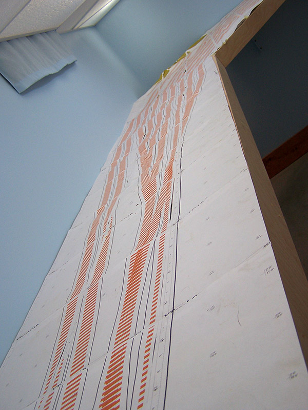
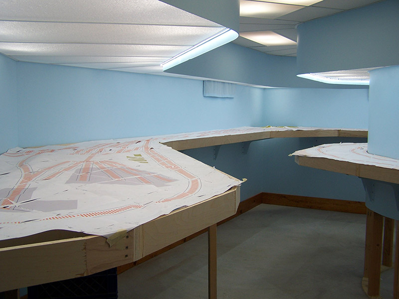
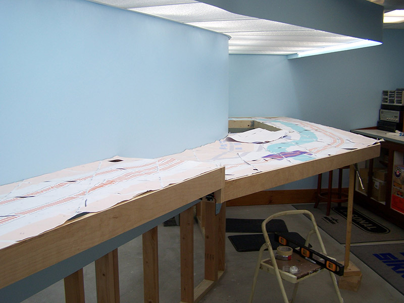
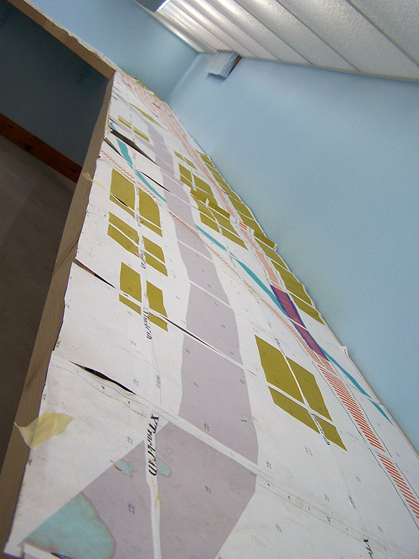
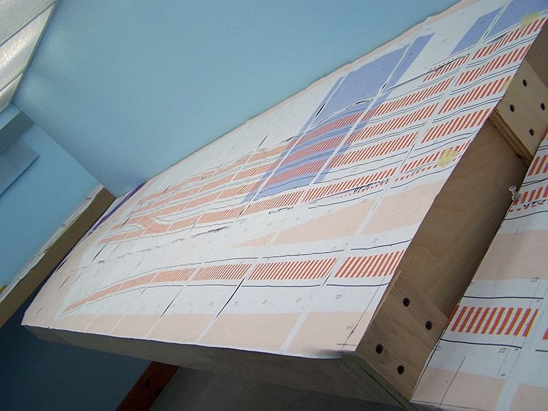
I have finally reached a point where the LK&O will begin to actually look like a railroad. It is time to build sub-roadbed and lay track. As you can see in the picture gallery below, the trusty old paper track plan is in place on the benchwork. The poor paper has been through a lot over the past three years. It spent two years on the floor being walked on, having benchwork constructed on top of it, and basically acting as floor covering. It also spent a year wadded up in the corner during a period of time when it wasn’t needed. The wear and tear has taken its toll but fortunately it has but one last duty before it hits the trash can. The plan will serve as my template for cutting sub-roadbed to shape and locating it on the benchwork.
It should be noted the lines I have labeled as sub-roadbed on the drawing are actually roadbed lines. Sub-roadbed is normally wider than the cork roadbed. Since I am placing sheet foam right up against my sub-roadbed it is not so critical the sub-roadbed be wider than the roadbed. Drainage ditches and other similar trackside features will be carved directly into the foam.
In case you are not familiar with the terminology:
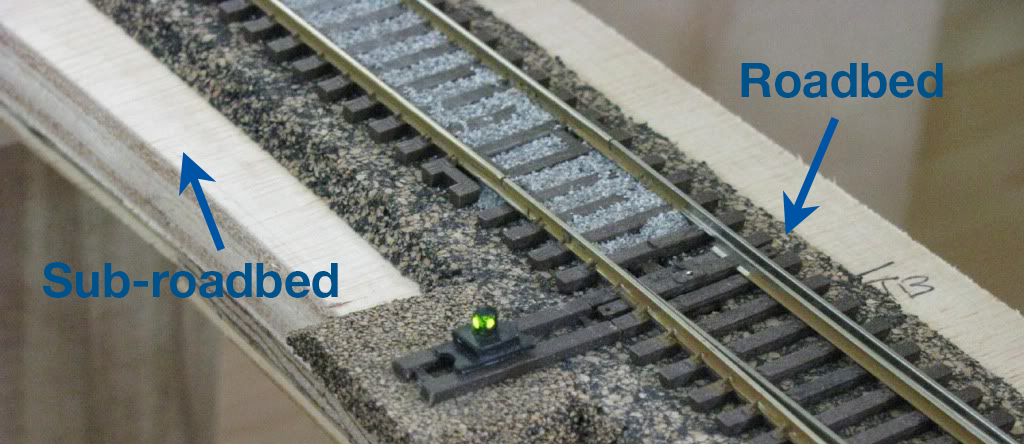
I found this track image on the web long ago. I do not remember who posted it. To whoever owns this picture my apologies for not being able to credit it to you. BTW the LED switchstand idea is killer! I absolutely must have these on my railroad.
EDIT thanks to Jas for pointing me to the LED switchstand site. Thanks to Bob Farrell for the slick idea.
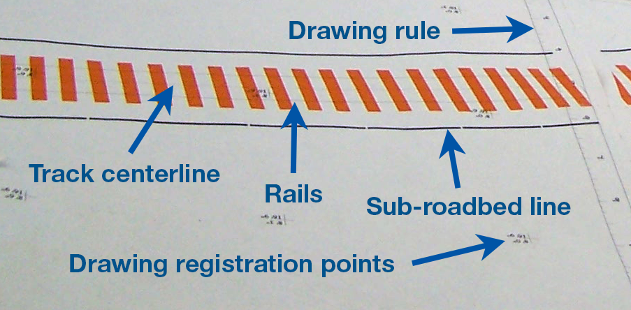
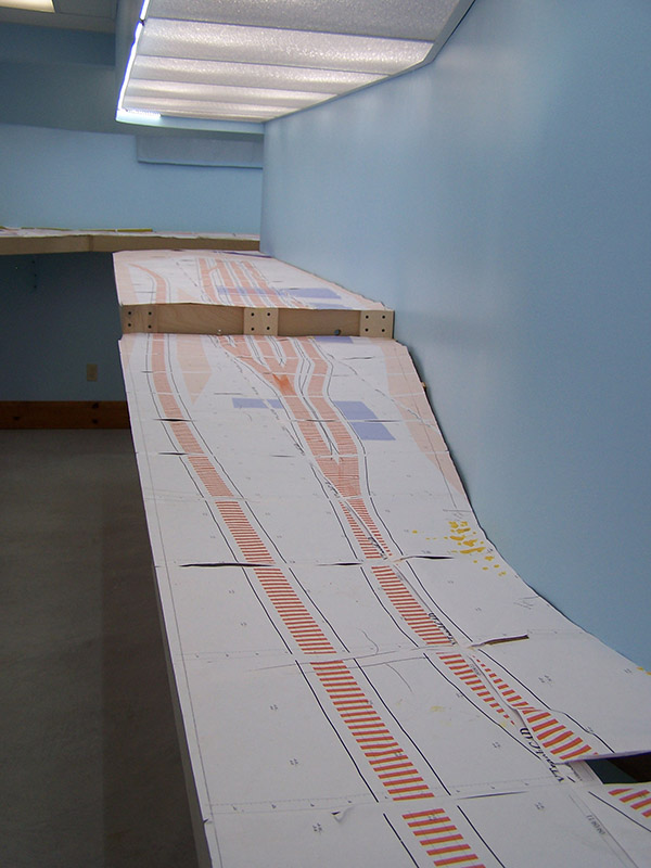
Closeup of the paper plan so you know what I am working with.
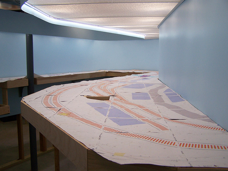
There are several places on the paper plan that have not survived the ordeal. I have to reprint some pages and splice them in to repair the damage before I commence sub-roadbed cutting. Alignment of the various pieces is important so I must make these repairs before proceeding. Once the paper plan is repaired the process I have in mind goes something like this:
- Reinforce with clear packing tape each seam in the paper where track crosses from sheet to sheet.
- Stretch and pin the paper plan tighter than it is now.
- Divide the plan into sections that can be cut from a single sheet of plywood (no section can exceed 8′ in length). Try to keep areas that have a high density of switches on the same piece of sub-roadbed.
- Using a razor blade, cut out the track along the roadbed lines printed on the plan.
- Mark alignment points on the crossmembers corresponding to the openings created by removing the track segments.
- When all track segments have been removed and all crossmembers marked the non-roadbed portion of the paper plan will be discarded.
- Trace and cut from 3/4″ plywood all sub-roadbed sections leaving 1/4″ extra on the ends. Locate the sections in their proper place on the benchwork. Refine the joining ends.
- Lay 2″ foam sheet in place aligning with front (or rear) edge of benchwork. From underneath trace outline of sub-roadbed on foam. Cut foam to shape. Place on benchwork.
- Temporarily place paper plan track segments back into position on their respective sub-roadbed sections. Locate switches. Drill throw bar access reference holes.
- Place temporary spacer blocks under sub-roadbed to bring top of sub-roadbed up to layout zero elevation (53″). Place weight to hold sections in place.
- Once all sub-roadbed sections are in proper position elevated with spacers and foam is positioned, locate and install risers.
One at a time, beginning with the highest track density sections:
- Move sub-roadbed section to the workbench.
- Install necessary roadbed (Midwest cork on mains, flat cork sheet in yard and on spurs).
- Tune switches as needed (gauge, point rail contact, frog flangeway depth, etc.).
- Solder feeders to switch rails (all) and frog. Solder jumpers to switch points.
- Locate and drill feeder holes in sub-roadbed.
- Finish drill throw bar access holes.
- Install track with acrylic sealant caulking. Test for proper wheel/truck movement.
- Install Tortoise switch machines. Solder wire lengths to Tortoise terminals. Solder frog feeders to Tortoise.
- Install track power buss termination. Install track power buss. Solder feeders to buss.
- Test all electrical.
- Install section on benchwork.
- Move to next section.
Joining track of one section to the track of the next section is an important consideration in this plan. There is no way I can work at such a precision level that the sections will just plug into each other like toy train sectional track. Alas, I have solved this problem. And engineered in a little slop room for me to work.
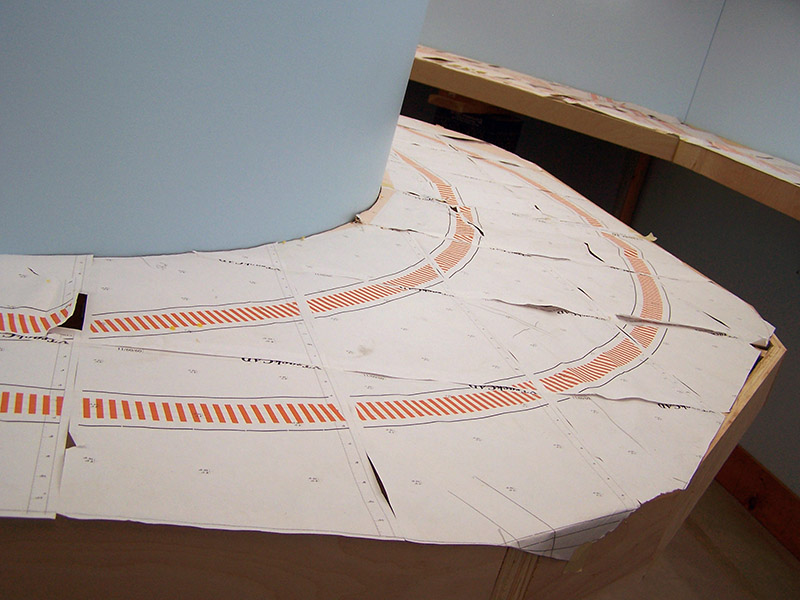
I will leave the single track sections between high density sections open until all high density sections are in place. Then I will lay the single track sections much the same as one would lay flextrack on any flat surface. These “interface” sections will have their track laid while in place on the benchwork. Any slight discrepancies in alignment can be compensated for in the interface section. At least that’s the hope. 🙂 Brittain Yard is longer than 8′ and, because it curves, is wider than 4′ hence it cannot be made from one section of plywood. The big curve in the classification tracks will be laid in place and serve as the interface in this otherwise high density area.
Well, that is the plan. I am about to see how well it works, or if it works at all! Here goes…

Alan looks great. One thing that you did not mention was your vertical separation between the mainline, sidings, and spurs and yard tracks. A layout that is being built as meticulously as yours might want to take this into account.
The following idea is not mine but was discussed in one of the track planning or great model railroad annuals. On the main line HO scale cork was used and topped with N scale cork to depict the “high iron”. Passing sidings were on HO cork by itself, and yard tracks and spurs were on N scale cork by itself. A transition section was used to go from one level to the next. All tracks when joining the main were raised to that level, the main was never lowered. So each lower grade of track would be raised to the level of the next higher level before connecting.
It is covered in great model railroads 2009 and called high green on the C & O in Appalachia. The man that built the railroad works for a prototype railroad and is either a dispatcher or signal maintainer, I can’t remember which at this point. He also sells CTC dispatching panels and makes some that are tremendously realistic looking.
If you have not read that article you may want to it is very well done.
Rob
Rob, your point is well taken. Actually, this is part of my plan although I did not state it as such in this post. My plan is to place mainline on HO cork (1/4″ I believe), sidings and high movement spurs on N cork (1/8″?), yard and lesser used spurs on sheet cork ballasted to appear nearly in the dirt. Does that sound reasonable to you?
Sounds like the same thing, three different heights for the three different types of track. I wish I lived next door so I could pop in from time to time and see how things are going, and operate on the layout when you get it further along. Fantastic work so far all along from plan to implementation. Definately the 5 star method for building a railroad.
Between all the work on the layout and your work on the blog to keep the rest of us informed how do you have time for a job and life outside the layout room?
Rob
I suppose the fact that I posted at 1:44 am and you replied at 2:54 am pretty much answers your question 😉
Sleep optional.
Alan,
Are you looking for this? In reference to the LED switch stand.
http://waynes-trains.com/site/Signals/OtherSignalStuff/LED-SwitchLamp.html
I sore the very same thing and book marked it myself too…
Jas…
Sweet! Thanks Jas.
Do we have a new update on the way, I feel like I should be handing you pieces of homasote or something.
Patience my friend. I have been doing a lot of extended business travel. Back home for a long spell now so railroad work can continue unabated.
Just kidding with you Alan. I am really impressed with your attention to detail and quality of execution in your plan. Although with trains , golden spike, etc looming on the horizon your blog has the feel of those old cliff hanger serials where one must come back next week to see what happened. I suspect I am not the only one caught up in this adventure.
Thanks again for posting such a great blog and sharing with the rest of us.
Rob
Alan,
I just saw the image of my LED turnout photo on your site. I am glad that you can use it and appreciate mentioning my name as the original designer of the LED turnout signal/lantern. I use this on almost all of my turnouts and had planned to try to produce a low volume production run of it. I did make a mold of one and a few resin castings.
Again, thanks for crediting me on the image. The image you used may have come from Elmer Wayne McKay’s website Waynes-Trains.com, where he used my write-up and photos as an entry in his ‘Tips and other Neat things’ tab.
-Bob Farrell
Bob, I am glad I saw your LED switch stands. It is a sensational idea and became an instant must have for me.
Alan … great site in helping me design new HO layout.
Do you think paper glued to Foamboard so I can draw plan full scale would hold up? I hate drawing small scale and rail programs suck. Guess I’m too old. I still have an analog calculator (slide rule). Plan is only 4 x 8 so I should be able to use fairly heavy paper so it would hold up to drawing/erasing, etc.
Roadbed would go directly on top of the paper. Also Foamboard mountains would also be glued directly to paper. Sounds OK, but doesn’t hurt to get better opinion
Thanks, Zene
Zene, I can understand why you might want to build on top of the paper plan but in the long run I don’t think it is such a good idea. Unless the paper is well glued to something rigid such as a plywood sheet then everything you build is subject to movement. Paper adsorbs moisture from the air over time so it gets curly. How about this approach… Draw your plan on the heavy paper. Once finalized, cut out the track design and use that as a template to mark your tabletop. Remove the paper and place track on the lines.
Alan … after quick consideration I will follow your example. It’s gotta be better. Thanks, Zene
[…] across a nifty idea for using bi-color LEDs as lanterns. It was first described on this LK&O post. The original idea belongs to Bob Farrell. I found it on Waynes Trains web site. Bob’s idea […]