This is a follow-up post to the original Tortoise relay project located here: https://lkorailroad.com/tortoise-control/
Remember this video?
I was unhappy with the relay wired point-to-point and glued onto the Tortoise as originally constructed. The exposed relay pins proved to be too fragile and easily bent causing short circuits. Add to this the circuit was wasteful with wire since I had to install very long leads assuring they would reach the fascia control panel. Would have ended up cutting off a lot of wire for the units close to their respective panel and you know how things work… would probably have found some leads too short for far away panels. And then there is the fact the Tortoise would require unsoldering to remove it from the layout if a problem develops. I played around a bit with experimenters IC boards but the hole spacing was too wide for the relay pin arrangement. I could make the relays fit with a little pin bending but it was a crude answer to the problem. A better solution was in order.
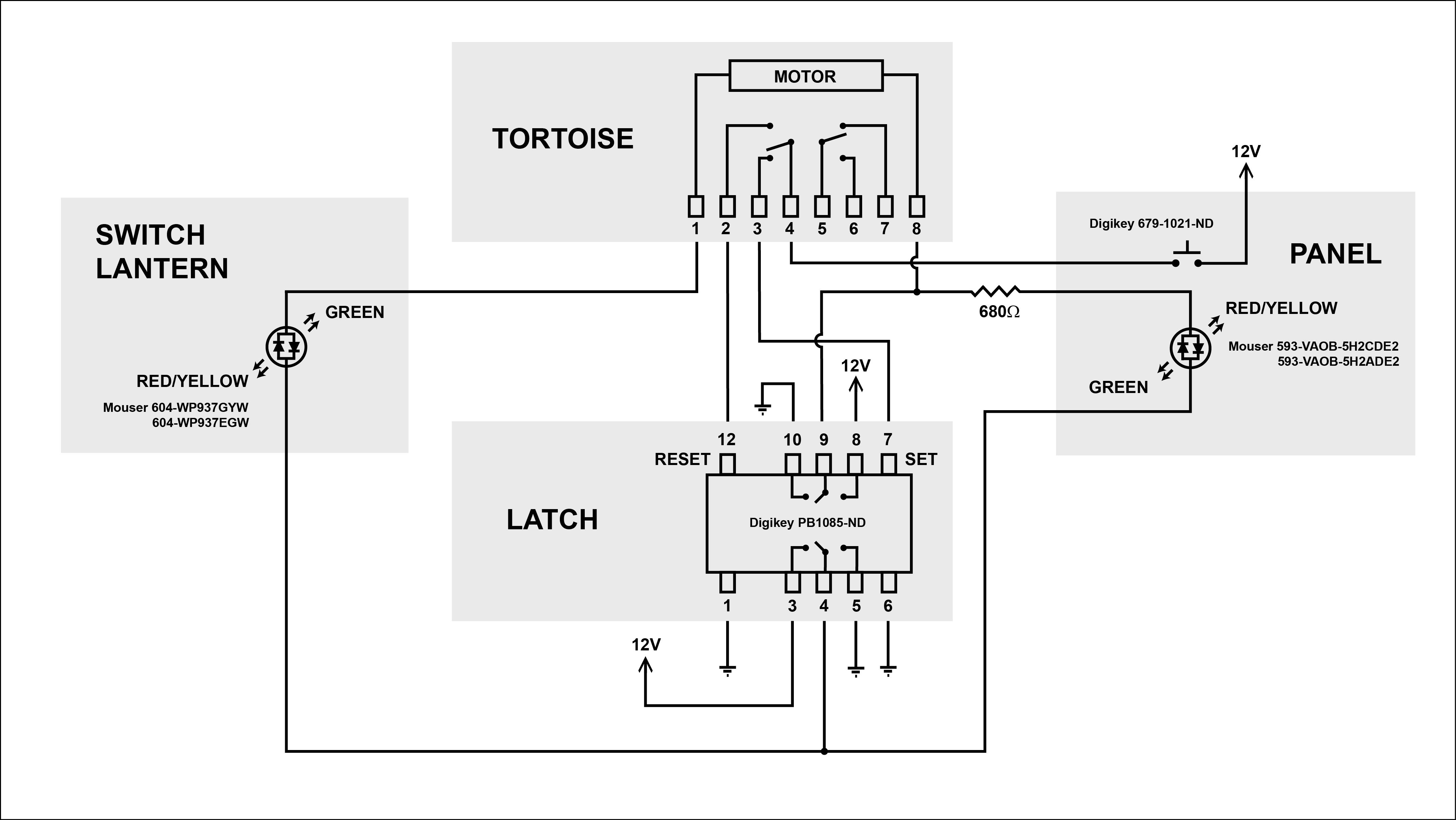
I decided to make a printed circuit board (PCB) to hold the relay. This permitted me to add a terminal strip so the Tortoise can connect to the layout with easily attached and, if needed, removed wires in screw terminals. Not directly related to making a PCB but an enhancement made at the same time is the addition of a second LED connection. Unlike the original LED connection which is in series with the Tortoise motor, the newly added LED connection incorporates a current limiting resistor on the PCB and is wired in parallel with the Tortoise motor. This gives me two LEDs that color change with switch position. The original series wired LED will now be in the switch stand while the new parallel LED will be on the fascia panel. There is a 2 volt drop across a LED. If I had placed two LEDs in series with the Tortoise it would have reduced the Tortoise drive voltage to 8 volts which will work but makes the Tortoise movement too slow and weak for my tastes. I really like the Tortoise action at 10 volts (one LED in series). There is another advantage to limiting the fascia panel LED with a resistor. Doing so allows me to tailor the resistance so all the fascia panel LEDs are of equal brightness.
Here is an updated schematic:
Here is the PCB mask file if you wish to make your own: Tortoise_control_PCB_mask
So, I set about making PCBs. In years past I have made PCBs a couple different ways. Initially I would draw the circuit on a copper board with a Sharpie pen, etch in ferric chloride, drill, and assemble. This process worked but was very limited by the fact I was drawing with a Sharpie. Drawing mistakes were a pain to fix and the etchant often undercut the edges of the ink. And truthfully, the boards produced this way looked very amateur. A better but more expensive method used UV photo-sensitive copper boards, a negative mask, and a source of strong UV namely a $40 bulb which I accidentally broke long ago. When done correctly this process produced a nice board but it was difficult to manage the exposure and etching. On more than one occasion my efforts yielded poor results. For the Tortoise PCBs I decided to try something new to me – positive resist board making.
Here is a video that clearly explains the process. With a few exceptions I used it as my guide.
I bought the pre-sensitized board and developer solution from Circuit Specialists. The exceptions for me from the video were:
- I used inkjet transparencies because I own an inkjet printer and not a laser printer;
- I did not use red light for the dark work. Instead I worked in the darkened train room with only the slight glimmer of light coming from under the door to see what I was doing. I also kept the sensitive side of the board pointed away from the under door light just to be safe;
- I placed masking tape guides on the picture frame glass to make it easier to align the mask and board in near total darkness.
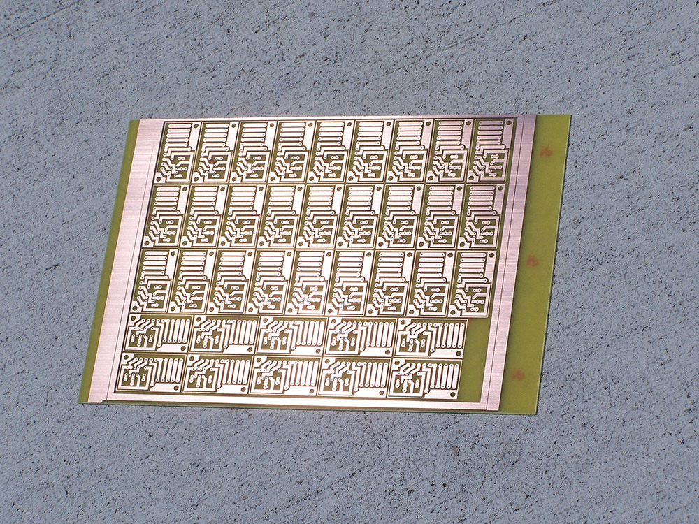
WOW am I ever impressed with the results. Check out how nice the board came out. And the process was so easy. I’ll detail the steps in the following post if you are interested in making your own. I am sold on the positive resist method. All of my future boards will be made this way. The results are the best I have ever produced.
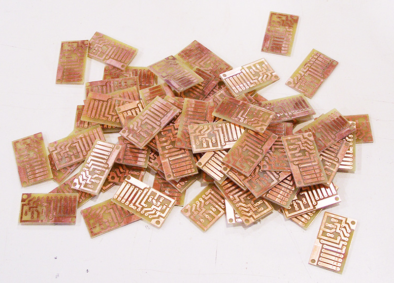
In the above image each individual board is only 1″ x 1-3/4″. The entire board is 8″ x 12″. The 8×12 board is good for 37 Tortoise boards. I made two of them for a total of 74 boards.
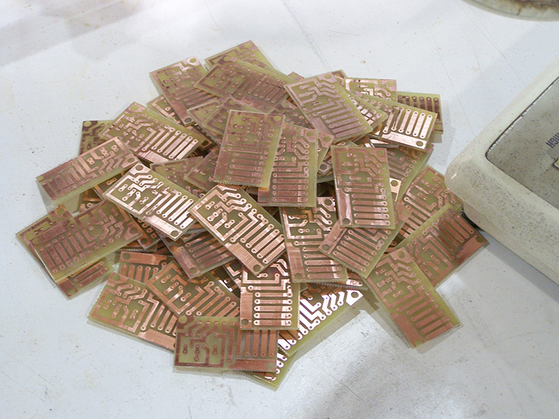
Next I cut them into individual boards with a jig saw fitted with a fine tooth metal cutting blade. I actually made for myself a poor man’s band saw by turning the jig saw upside down clamped between a pair of 2x10s. The foot of the jig saw became my table and I was able to feed circuit board into the blade as if it were a band saw. Rude, crude, and socially unacceptable but it worked great. No, sorry I did not take a picture and I am not sure I would post it if I had. 🙂 A little edge sanding on the disc sander cleaned up the edges after cutting.
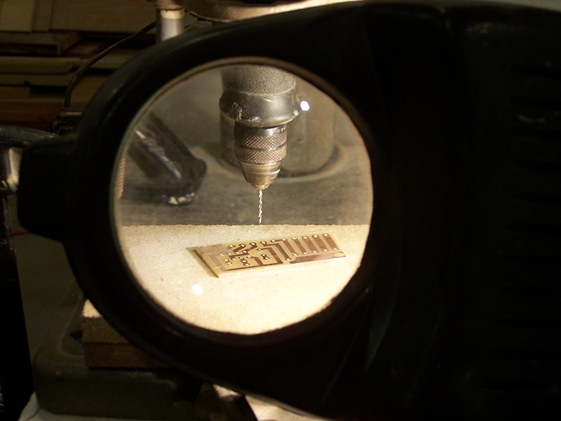
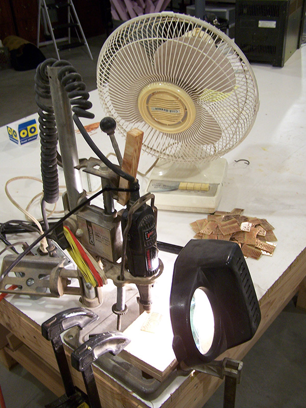 Drilling the boards was easy but oh so monotonous. A total of 2220 holes were drilled to make 74 boards. With the Dremel coerced into a drill press attachment made for a hand drill I set about drilling. Notice the mass of rubber bands on the drill press? My solution to rid the fixture of slop. Can’t use a drill that has more side-to-side slop than the diameter of the bit! Speaking of bits, a 0.030″ bit was used for all of the holes except the terminal strip and the 14 gauge supporting connections. The terminal strip required 0.040″ holes while the large copper necessitated 1/16″ holes. After drilling, the boards were lightly sanded with 320 grit sandpaper to clear drilling burs and then final cleaned with lacquer thinner to remove any hand oils prior to soldering.
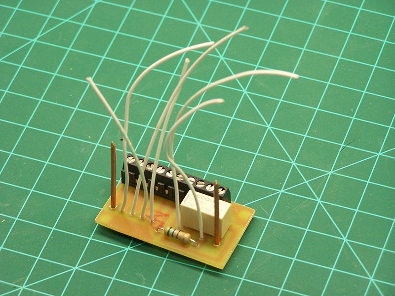
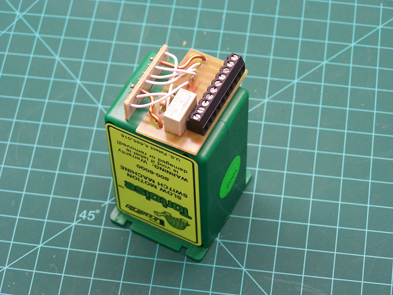
Here is a finished board with relay, terminal strip, and LED current limiting resistor installed. The two 14 gauge bare copper wires are both conductors and the physical support to mount the PCB to the Tortoise. No gluing to the Tortoise with this design. The board is held tightly against the Tortoise by the 14 gauge wire.
 Finally, a finished Tortoise assembly ready for mounting on the layout. The screw terminals provide attachment of the fascia panel switch and LED, switch stand LED, 12 volt Tortoise power, track power, and frog juice. This is a much cleaner, more reliable method than the old point-to-point wiring of the original model.
Now all I have to do is make 71 more just like this one!

Alan, You are truly a maniac! I have been following your layout progress for some time and I am always amazed at your capabilities and your attention to detail, etc, etc, etc. But this latest post is over the top! Makes me wonder if there is anything you cannot do. Please continue to astound.
Jeez David, you make me blush. There are plenty of things I can’t do. Just ask my wife… she has a list. 🙂
[…] There is a follow-up to this post that describes further refinements made to the Tortoise control. View it here. […]
Dude…you are so out of my league. I’m so electronics deficient that I don’t even have a smart phone and you’re making PCB’s…As David stated, you are over the top. Someday your layout will be a GMR staple.
Jeff in Plymouth, IN
Alan,
Thank you posting this update, I have been looking for a way to make printed circuit boards and this shows me everything I will need. I have a plan to make an indicating display for a double slip switch, I believe I have figured out the control scheme and the display I just a circuit board for the display to allow me to mount everything.
I also wanted to ask you what program did you use to draw the circuits with? Thanks for any information and keep up the great work.
Scott,
I used Adobe Illustrator but any graphics program will do. Make sure the pad spacing on your art matches the pin spacing of the components.
I’ve been wondering a bit about your plans for your roster of locos and freight cars. AC&Y had one H15-44 (#200), which they released in HO. They also had 3 early H16-44’s which Atlas also released (#201-203). Then they had three intermediate H-16-44’s (#204-206) which Atlas didn’t release in AC&Y colors; and AC&Y had two late H16-44’s (#207-208) which have been available from Pennsylvania Scale Models (Bowser) and Bachmann; but those weren’t released in AC&Y lettering. Of course, nobody has released an H20-44, so that’s a problem too.
So it appears that you have a mix of FM H15-44 and H16-44 locos that is different from AC&Y’s actual roster. How do you plan to form these into a coherent roster on your model railroad? Will everything be lettered LK&O, but using the AC&Y-inspired paint scheme? Will it be two railroads — AC&Y and LK&O — with similar rosters & paint schemes, and cooperative run-through arrangements, but separate ownership of engines? Will the road numbers be complementary? For example, will AC&Y 200-208 be numbered correctly, with comparable LK&O engines be numbered 250-258? Same question in regard to cabooses.
Maybe I’ve missed this in your earlier postings.
Just wondering.
Tom
Tom,
It is a bit hard to explain. LK&O is merely my name for the railroad as a whole. The initials are derived from the three LDEs I selected. LK&O identification will not appear anywhere on the layout in modeled form however it will appear on the fascia control panels. The power will be AC&Y, WM, and GT as these are the railroads depicted. Well, at least snippets of these railroads are on the layout. AC&Y and the Akron OH area represent the greatest percentage of real estate.
I purchased the Atlas H16-44s early because they are out of production and getting rarer by the day. Not to mention more expensive. The WM and GT power I can purchase anytime.
Not being a rivet counter I will be plenty satisfied to simply renumber the Atlas locos 200-208. The differences in appearance of the real locos is so trivial I am not worrying about it. Same for the AC&Y cabooses.
Since AC&Y Brittain Yard is modeled it will appear to observers the WM and GT power are run-throughs or I suppose possibly lease units even though the AC&Y never had any real life relationship with either of the other railroads. They do in my world. 🙂
You are correct about the H20-44s. They are available in brass but collecting those can get quite spendy. For now I will have to live with no H20-44s on the roster.
Just came across this really outstanding site and the recommendation/directions for push button control of the Tortoise machines.
I have used Rob Paisley’s 556 IC solution which includes a pre-printed board and all the parts to control 4 machines for about $24 delivered. Some assembly required as they say. For the most part it works ok but as mentioned in an earlier post a lot depends on the quality and consistency of the parts.
I wanted to switch from toggles to push buttons because I wanted to control the turnouts from either side of my layout. Couldn’t think of a way to make the toggles work together so I went the push button route. Wish I would have seen your solution sooner as it is elegant and simple and uses only one button where as the IC setup uses two. Any future expansion will use your twin coil relay method. Thanks for your wonderful and well written site and brilliant ideas.
I’m blushing. Thank you.
These have been really useful! I made some on my CNC router and they work great! It makes everything look so uniform have push buttons on all my panels! and its also nice i can operate the tortoises from multiple locations!
Glad to hear it.
I sent you a message earlier today about part numbers for the Tortoise machine circuit. I was able to find these part numbers after I was able to enlarge your image. However, there is one part number I have not found or have missed. It is the terminal strip that goes on the circuit board. Can you help me with that?
Thanks you!
Sincerely, Kennedy
Kennedy,
The connector is Molex #39357-0010
https://www.findchips.com/search/39357-0010
I bought mine from onlinecomponents.com