There is a follow-up to this post that describes further refinements made to the Tortoise control. View it here.
While I cut the final pieces of sub-roadbed I am thinking through the next phase to come – track laying. For regular readers of the LK&O blog you know the plan is to build each track “section” on the workbench for transfer to the benchwork once complete. Think of it as trackwork modules. Each module will be entirely complete before being placed on the layout. This means all electrical and mechanical components must be mounted and working.
I am requesting your input, please.
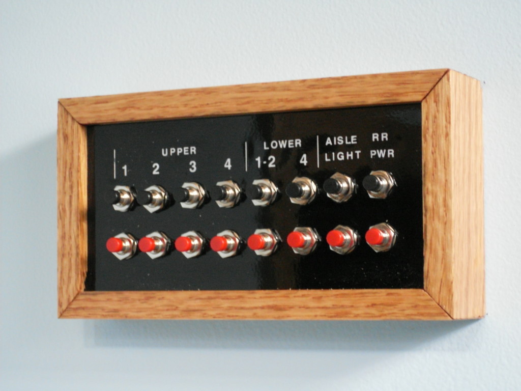
Starting with the very first section I will need to mount and make functional the Tortoise turnout machines. I want them controlled with the same pt# momentary contact push button switches I used for the lighting setup. They will be fascia panel mounted with multiple panel/switches for the same turnout in some instances. The fascia panels will have a track diagram with green/yellow LED position indicators. Nothing revolutionary there, huh? I should mention, there is no desire for DCC or computer control of the turnouts.
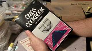
I am going to breadboard the schematic I found on the Internet (below) to make sure it performs as expected. Although I don’t totally understand them, I have had great luck building circuits taken from my old copy of CMOS Cookbook (now very tattered and torn from use). I know there is likely many circuit ways to go about this but I tend to favor CMOS because the circuits always seem to work even with my very limited understanding.
In addition to being CMOS, the feature that I really like about this circuit is the defined relay state during power up. This will allow the entire railroad to have a default power up turnout position. Parts from Digikey and circuit boards from Pad2Pad are within budget for this part of the railroad construction so cost is OK.

If you have electronics knowledge and/or a better way of controlling the Tortoises I invite you to comment. I don’t have to make a firm decision for a couple months or so. Thank you in advance.
— UPDATE #1–
More than one person on the modelers forums have suggested the circuit below. Thoughts?

— UPDATE #2–
There seems to be disagreement within the modeling community as to whether or not the 556 based circuit will power up in a defined state or not. Some say they have built the circuit and it does while others say it does only because of slight manufacturing differences in the component values. In other words, power up reset happens as a result of component choice/quality/tolerance/value/whatever instead of by circuit design. It is times like this it would handy to be an electrical engineer. 🙂
— UPDATE #3–
Don’t you just love it when you have an epiphany? Two of them back to back is just down right spectacular. That happened to me today.
Realization #1
Having a defined power up position of turnouts might not be such a good idea. What if a train, for whatever reason, is parked straddling a turnout? I may be setting myself up for a derailment as I turn on the railroad. Hmmm, maybe I had better not do that. Aborting the defined power up position of turnouts I set about rethinking the Tortoise control system.
Realization #2
Bistable dual coil latching relay. Tie one side of each coil to ground. Tie the other side of each coil to the contacts on one of the Tortoise’s SPDT switches. Supply V+ to the push button. Connect the push button to the center of the Tortoise SPDT. When the Tortoise moves it will change the push button from being connected to one of the latching relay coils to the other. The Tortoise will do the coil assignment. Pressing the button triggers whichever coil is presently connected. The relay moves in only 4ms. No way the Tortoise contacts will open faster than the relay actuates.

Is that simple and foolproof or what? No ICs, no circuit boards, nothing more than a switch and a relay. I am ecstatic!
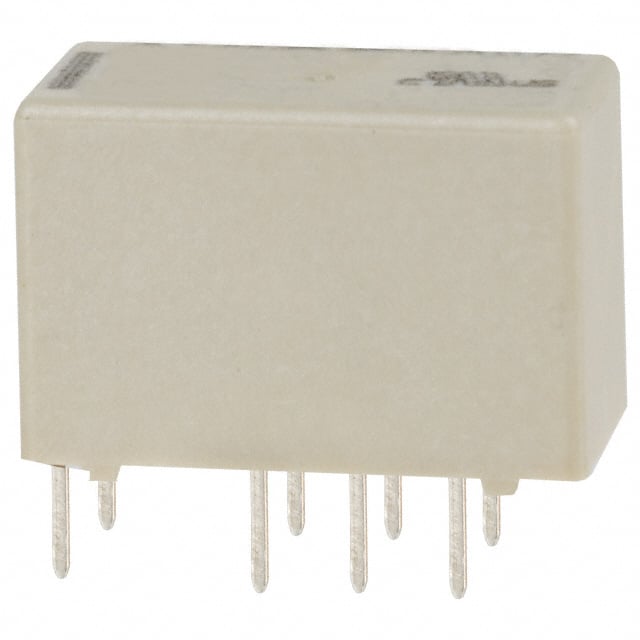

Digikey pt# PB1085-ND $1.96 ea.
Digikey pt# EG2031-ND $1.32 ea.
Total per Tortoise $3.28
I’m putting away the breadboard. This is a done deal.
— UPDATE #4–
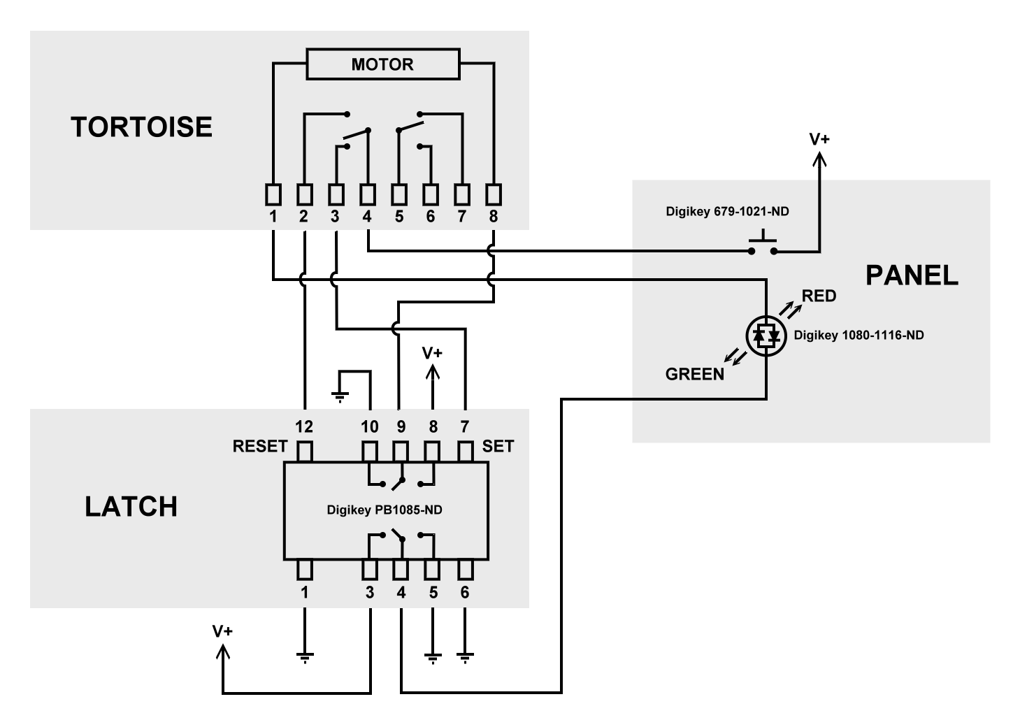
Schematic for the Tortoise control system. Ordered a single relay from Digikey so I can prototype the circuit just to make sure it work as I expect it to.
After checking my Digikey receipt from when I ordered the push button switches for the lighting control I realize the part number shown above is wrong. Too bad, it is a much less expensive switch. The correct pt# is 679-1021-ND as shown in the schematic. Adding in the LED the correct cost is:
Digikey pt# PB1085-ND $1.96 ea.
Digikey pt# 679-1021-ND $2.20 ea.
Digikey pt# 1080-1116-ND $0.23 ea.
Total per Tortoise $4.39
— UPDATE #5 —
A working pre-production version of the Tortoise control. I am ready to mass produce them in preparation for this winter’s marathon track laying session. Enjoy!
— UPDATE #6 —
You get the Tortoise and relay all wired up, turn on the power, and nothing happens when you press the button. The problem may be in the confusing way I inserted the wires into the Tortoise circuit board in the video. The fix is simple. Reverse the positions of the wires on the #1 and #8 pads on the Tortoise. Now push the button again. Ah, that’s much better. Happy Tortoising! I updated the schematic on this page to help clear up the confusion.
— UPDATE #7 —
For readers wishing to use the latching relay & pushbutton Tortoise control circuit described herein I have found a much lower cost supplier of the latching relays – Arrow Electronics. The average street price of the relays has went up considerably since I first prototyped the circuit. When it came time to order in quantity I discovered the popular asking price hovering around $2.40 ea. Arrow shows them on their website at $1.79 ea. I ordered 82 relays. Much to my surprise the invoice at checkout showed $1.26 ea. What a great deal! Essentially a 50% discount from street price. Arrow shipped within 2 days, were safely packaged in IC tubes, and are the same TE Connectivity part sold elsewhere.
Arrow Electronics: http://parts.arrow.com/
Latching Relay at Arrow: http://parts.arrow.com/item/detail/te-connectivity-ltd/3-1393788-6#cnyg
— UPDATE #8 —
The original design utilized wires soldered directly to the pins of the relay. In actual practice this has proven to be too fragile. It doesn’t take much of a bump to a wire to cause the relay pin to bend and make contact with an adjacent pin. The relay pins are terribly small. Two pins touching each other is of course not good. To remedy the situation I am soldering the relay to an IC Experimenter board. These little boards are very popular and can be found just about everywhere. My first exposure to them was at Radio Shack. Over the years I have used countless numbers of these for making little circuits.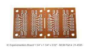 This time around I needed a bunch of them. They are supplied 2 boards hooked together meant to be used as is or broken apart at the perforation for circuits using only a single IC. 50 boards split in half yields 100 relay boards. Since I needed so many the local Radio Shack was not the place to buy. One, they don’t stock a ton of them. Two, they are expensive. One of my favorite electronics haunts, MCM Electronics, has the lowest price I could find on the interweb – $1.00 ea.
The relay pin spacing is not exactly the same as an IC so the relays don’t just drop into the board. The spacing is really close. Only a little S-bend in the relay pins is needed. Having the relays soldered into these boards will eliminate the fragile pin problem. The wires, also soldered to the board, can be rough handled without fear. As with the relay, a blob of glue will attach the board to the Tortoise. Off I go. I have 100 relays boards to solder up!

I have been following you layout and I believe that your website should be the process standard on how to build a layout.
I also like your push button lighting system.
From my experience building the control panels for my clubs layout, I have to ask the reason for wanting your tortoise controlled by puch button? You did comment there is no desire for DCC or computer control of the turnouts.
Just food for thought, but I found using mini Double Pole double Throw (DPDT) switches the way to go with stall motor switch machines. In fact our club switched to tortoise machine to simplify the wiring. Not only is the wiring simple, and there is no requirement for LED indicators as the electrical switch also can be used to indicated which way the turnout is thrown.
I have to admit that there is cool factor with the push button, but I dont think it is worth the work, unless you want DCC control.
If you did want DCC contol using a stationary decoder, then most have a provision to install a push button switch to control the turnout at track side.
Just food for though. If you do build your push button tortoise control, it will be cool.
Art
Art,
That’s one heck of a compliment there. Thank you.
You have it right. The push button idea really is just for the cool factor as you say. Toggle switches give such an old school home built look. Or at least they do in my eyes. You are correct it would greatly simplify wiring. This may sound a bit strange but since building the light switch assembly and having used it for some time, I really have come to like the fact that such a light touch is required to operate them. You barely have to touch them to close the contacts. I know, I know, who cares about how much effort it takes to throw a switch? It’s an ergonomic thing I suppose. Sort of like the difference between a car door that has to be slammed to latch (think US cars prior to 1990) and car doors that latch with just a gentle closing (think 2012 Lexus). Both doors close and latch but there is something nicer about the Lexus door. Does that make any sense?
Cool factor wins every time.
I have built the 556 based circuit to control LED indicators for a solenoid switch machine. I had problems with it powering up in a determined state. Never developed a solution. I would just throw the switch to ensure the LED agreed with the switch on power up. Because your indicator is integrated into the motor control circuit then the LED will always indicate correctly.
Keep up the great work.
Art
Alan,
While I would go with a toggle switch I understand your wanting to use the push buttons. Like you my budget is tight and I have found a few electrical websites you may be interested in versus Digikey.
The first website is: All Electronics Corporation
All Electronics has push buttons for $.85 a piece with different colored buttons (black, red, blue, green, white & yellow). I have used them and they are reliable and quick to get parts sent out.
Another website: Futurlec
Futurlec has push buttons for $.45 a piece but there are a couple of things, you only have two button colors (black & red) and one is a NO switch and the other is a NC switch. The other thing is that they are located in Bangkok with offices around the world. I have ordered from them and, like All Electronics, they are reliable and quick to get the items sent to you.
I hope this helps you out and I hope you get this before you make your purchases from Digikey.
Regards,
Scott
Thanks for the alternate sources Scott. I am familiar with All Electronics. Have ordered from them in the past. My only gripe with them is the extremely limited information about each product and the often inability to buy the same product years down the road. Digikey, while being more expensive, provides detailed dimensional drawings and complete datasheets. Also I have yet to not have success reordering something at a later date. That is what has prompted me to patronize Digikey so much.
BREAKING NEWS
Scott sent me on a quest to find the components less expensive than Digikey. Thanks Scott, it paid off. The latching relay and LED are tough to find. Where found, they are about the same price as Digikey. Not enough difference to worry about. The push button switch is a whole different story. Found them listed as discounted overstock items at Allied Electronics. $1.05 ea instead of $2.20. 50% savings. Placed an order with Allied for 100 of them. Thanks for saving me $100 Scott!
Alan,
We are converting a 100′ by 40′ club layout to DCC. Present layout is DC with two elevated switch towers controlling parts of DC on layout as well as turnouts.
We want to move turnout control to floor level near operator.
Do you have a completes part list and drawings for your control as a final version. I believe it might solve our problem.
Ray Theobald
Asst. Super.
SCMRR (Manchester, CT)
Ray, I sent you an email containing the information.
[…] to this post for detail regarding the Tortoise control. There is a follow-up post with further […]
[…] This is a follow-up post to the original Tortoise relay project located here: https://lkorailroad.com/tortoise-control/ […]
Great site and great work. I am wondering if diode matrix routing control could be implemented with your single push button set up? I am no expert on this but did install it with twin coil machines on an older layout.
One other question. I would like to have an LED on each leg after the switch rather than a single “bi-polar”. Can this be done?
I have been looking for a Push Button solution and so far yours looks the best AND most affordable. THANKS!
Sure, why not. I see no reason why a diode matrix arrangement wouldn’t work.
For your multiple LEDs simply wire 2 conventional LEDs anti-parallel (cathode to anode, anode to cathode). Use the pair of LEDs in place of the single bi-polar.
Dan,
After giving it some thought I don’t think diode matrix will be easily implemented due to the toggling nature of the momentary push button switch action. Not saying it can’t be done, just that it may not be as straightforward as desired.
I think a better way to go about it would be to use a logic circuit NAND gate. One input fed from the panel LED lead and the other from the diode matrix. This would actuate the Tortoise only if it is not already in the correct position.
https://en.wikipedia.org/wiki/NAND_gate
alan said:
For your multiple LEDs simply wire 2 conventional LEDs anti-parallel (cathode to anode, anode to cathode). Use the pair of LEDs in place of the single bi-polar.
If you use two R/G LEDs in this configuration,then they will show Red and Green in the two legs of the turnout. Our club has had this for 30+ years.
Another possible solution!
One complication to dual R/G LEDs with the above Tortoise control is the single current limiting resistor installed on the Tortoise relay board. Should remove/shunt the one resistor and place two resistors, one for each R/G LED. Otherwise there would be one resistor limiting two LEDs in parallel – no means of individually controlling brightness.
Even though I am a bit confused, I do appreciate all answers to my questions. I might have some additional questions before I purchase components.
Questions on the LEDs.
Dr JolS says: “they will show Red and Greed in the two legs”. Does this mean that when one leg is selected it will show Green and the other leg will show Red? Meaning there will always be two LEDs on and each will toggle between Green and Red? I am not sure that I care one way or the other but just thought I would ask.
alan says: “no means of individually controlling brightness” – unless modifying resistors. Is this a big deal to have individual control? If it is, is it a big deal to make the modifications?
Remember I am not an electronics guy.
I will come back on Routing and I read the supplied information at the website link provided.
Thanks again!!
Yes, you understand DrJolS as I do. Both LEDs would be on with the colors alternating with switch position.
LEDs in parallel with a single limiting resistor is bad for a few reasons:
1. Manufacturing tolerances are wide enough to cause brightness differences.
2. Resistor has to be sized for one LED current meaning with two LEDs the most current they will get is 1/2 their max, 3 LEDs 1/3 A, 4 LEDs 1/4 A, and so on.
3. Different color LEDs have different forward voltage drops. One color will begin conducting before the other.
This page has a good explanation:
http://electronics.stackexchange.com/questions/22291/why-exactly-cant-a-single-resistor-be-used-for-many-parallel-leds
Alan,
I am attempting to wire the tortoise switch machine to the momentary push button as shown in your video. This is my first foray into electronics and I am struggling even with us use of a breadboard. After studying your video I cannot determine where the wire from the #1 lead (green/white wire)(v+) on the latch connects nor can I determine where the #10 (green wire)(-) on the latch connects.
Any assistance you can provide would be greatly appreciated.
Green wire is connected to 12v negative of your power source – #1, #5, #6, #10 are all connected to 12v negative.
White/green wire is connected to 12v positive of your power source – #8 and #3 are connected to 12v positive.
Does that answer your question?
Alan,
Thank you! Just what I needed.
Alan,
I have followed your diagram, checked and rechecked, yet cannot get it to work. I have the latch attached to a breadboard and the positive wires going to a terminal block and then to the transformer. I did the same with the negative wires.
I have checked my transformer and tortoise switch machine and it does work if I try the conventional wiring.
The push button also works.
It seems that whenever I put in either the #3 or #8 positive wire it shorts out.
Sorry to bother you, but I really want to do this, but cannot figure out what I am doing wrong.
I even have tried switching out the latch with another one with the same results.
Appreciate your patience.
Brad,
1. When you say transformer you are talking about a DC power source, correct? The circuit won’t work on AC (the output of a transformer).
2. Check to make sure you haven’t accidentally connected pins 4 or 9 to ground on the latch. Pins 4 and 9 go to the Tortoise motor (pin 9 via the LED).
The circuit as shown is known to work. Check your wiring and connections carefully.
Alan,
Thank you for the great resource. I want to do this for my Atlas Snap Switches and I have 2 questions:
1) What power supply do you recommend?
2) Are there any changes needed to make this work for the Snap Switch?
Thanks again, this has been a huge help.
How about 3 questions 😀
What about using something like this?
http://www.ebay.com/itm/1-Channel-12V-Latching-Relay-Module-with-Touch-Bistable-Switch-MCU-Control/172557291576?_trksid=p2385738.c100677.m4598&_trkparms=aid%3D222007%26algo%3DSIC.MBE%26ao%3D1%26asc%3D20160908110712%26meid%3D0a5373728e584af889df7d4bbf8695e7%26pid%3D100677%26rk%3D1%26rkt%3D30%26sd%3D172430103650
Will,
My Tortoise circuit won’t work with Atlas twin coil machines. It only works with stall motor machines. Twin coil machines require a momentary pulse of current to operate. If continuous current is applied, as my circuit does, a twin coil machine will overheat. Same applies to the eBay module you reference. It is possible to arrange a latching relay and push button switch in a manner that will operate a twin coil machine but that is not what is depicted in this blog post. I might be able to create a schematic of this arrangement for you if you are interested.
Thanks Alan
Any help you can provide would be great. My goal is push button control with single lights.
What type of lights? Bulbs, individual LEDs, single bi-color LED, other?
I’m still trying to figure out all the block lighting so I am not 100% sure, let’s go with individuals since most the (cheap) lights are multiple bulbs.
Will, a schematic was sent to your email.
I am totally impressed of all the things You are making here. It’s fantastick what you are makeing. I have made some rc cars(1/32-35) and now I’m dealing with a garage for the cars. I have mounted lights outside and inside(LED’s) and I wonder if You could be so kind to send me a drawing of how to connect one switch to each of the LED’s to switch on/off the lights. I have the same relay with two coils that You use and some other relays. I use 5 volt DC for the garage door up/down motor.
I have worked as a technitian for many years but now I’m struggeling with my memory….so heeeere I am.
Sigmund, I’ll need a little more information to help you. I’ll send a PM.
Help! I bought all the components you stated in this article. I watched the video, but I’m still lost. I want push button and not toggles to throw the tortoise. I want to use 1 bi-color 2mm led. But not understanding electrical drawings, I can’t figure out how to wire all this together. The relay show in the video looks like 8 pins and not 10. I cant figure out the schematic and the video. They appear different. Again excuse me for my lack of understanding. I think you have a wonderful idea and the video was great, but I’m still lost. On the schematic I see wires going nowhere which really throws me. Could I impose upon you to tell me which pin on the tortoise goes to what pin on the relay and how the push button and led are wired in as well.
Again, I apologize for my stupidity. But I really want to use the push button and not a toggle. You seem to be the only answer to my problem. Please respond. Thank you in advance. Jim
Hello Jim.
Use the updated 2nd generation schematic on this page: https://lkorailroad.com/tortoise-printed-circuit-boards/
The connections in the schematic that appear to go nowhere are the + (pos) and – (neg) wires going to a 12 volt power supply. Positive uses an up arrow, negative uses a down arrow. 2 of the relay pins are connected to positive, 4 of the relay pins are connected to negative. Are those the wires to nowhere you are referring to?
In the video the relay appears to have only 8 pins because I solder bridged the ground pins together instead of using individual wires to each pin. The relay does in fact have 10 pins and the schematic reflects this. Also, the video uses a first generation schematic whereas the link I supplied in the comment is 2nd generation. Either accommodates bi-color LEDs but you should use the 2nd.
For Tortoise and relay pin numbers look at the referenced schematic. They are numbered on the schematic to match the numbers on both devices. Keep in mind you will need every wire/connection shown on the schematic for it to work. There are more connections than just relay to Tortoise.
Write back if you still have trouble.
I just found this page and I love it. I ordered few parts to experiment with. I am wondering why no-one mentioned pins 5-6-7 to power the frog. I haven’t tryed it, but this seems like an elegant solution.
Nick, I do use 5, 6, and 7 for frog power. Sadly that piece of information is buried elsewhere on this blog. Even I can’t find it right now.
If I wanted to control the tortoise with two push buttons and omit the LEDs, how would the circuit change? This is for a Free-Mo module application.
This is wonderful info, thanks for providing it.
Bill, very easy to do.
Wire additional switches in parallel with the original switch. Substitute a wire in place of the LEDs.