Ring! Ring!
No, that isn’t the telephone ringing. It is my power distribution system. Except this ringing can’t be heard with you ears but rather only measured with an oscilloscope.
A couple of the guys on the train forum brought up the fact that my wiring of the power buses in a loop arrangement may have some unintended consequences. Multiple current paths may not be such a good idea after all. So, I headed over to the electronics forum where the whiz kids hang out to get their take on the system. Turns out the railroad forum guys were right, sort of. The online community has once again helped me tremendously. The problem with my system is not so much that the wires run in a big loop, although the electronics guys all agree it is not good design practice, but rather the fact my system has no dampening.
As it was explained to me, when a load is first placed on the bus it will cause a voltage drop. The power supply will respond by increasing the voltage. However, due to the length of wire between the power supply and the load, with the resulting capacitance and inductance of the wire, the voltage will overshoot when it recovers. This causes a viscous cycle of over/under correction until some time elapses and the system settles down. This over/under oscillation is called ringing. The amount of ringing effect is largely determined by the voltage rise time speed and size of the load. At least that is how I understand it to work.
One of the guys on the electronics forum, Adam, was kind enough to set up a simulation of my system using what little information about it I could provide him. Here is his reply:
Right here is the formula I used to roughly calculate your system.
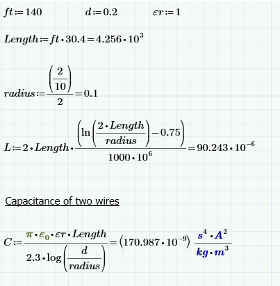
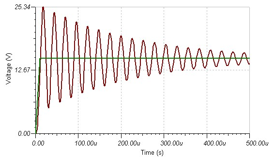
The first circuit I used shows ringing without a load.
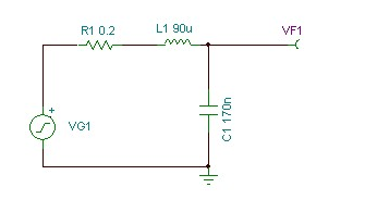
This is with a 10us rise-time which is quite fast, I think you will have more delay in your circuit than this. This doesn’t include any capacitance the rest of the system has, adding this will stretch out the overshoot and reduce the amplitude slightly. But the root cause of this overshoot is the rate of change of the current in the system and lack of low damping. So you have two options, increase the rise time which I think your system will naturally do, or add some damping which I also think your system will do.
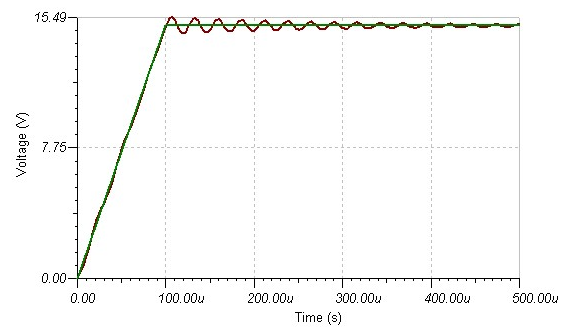
This again but with 100us rise-time, almost gone.
And this one with a 10R load.
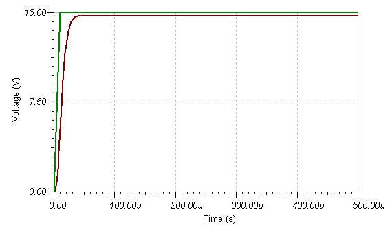
The simulations show rise time is the culprit. Unfortunately, I have no way of predicting or controlling rise time. That is dictated by the trains. Much back and forth discussion ensued about using a RC filter (resistor and capacitor) to suppress the surges however the lack of necessary information about the bus and loads made it impossible to determine the correct values.
Pre-loading the system (shown in last trace) was decided to be the best solution. This will be a 1A load that is present all the time. It will act somewhat like a shock absorber on a car suspension. Just as a shock absorber keeps a spring from bouncing back and forth after a bump in the road, the parasitic load on the bus keeps the voltage from bouncing up and down after a new load is placed on the system. The trace shows the system response with a 10 ohm pre-load which would place a 1.7A load on the bus as an example. You can see it smooths out the ringing quite nicely. Keeping in mind every bit of damping load I place on the system reduces the current available for trains. My power supply is limited to a maximum output of 7A. Of course I could simply replace the power supply with one of higher output but I would rather not do that for cost reasons. Adam suggested a 1A load would be sufficient.
So it looks like I am not quite done yet. I have to add a 1A load at the furthest point in the bus from the power supply for each of the three buses. I think I have an excellent use for these loads. The north helix is at the right spot along the bus. I would like to have lighting inside the helix for those times when I am performing routine maintenance like track cleaning and for the possibility of fixing a derailed train. Looks like my 1A loads just may end up being lights inside the helix!
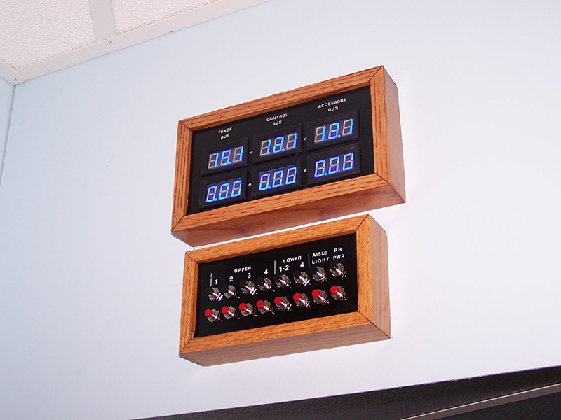
Oh, by the way I fixed my staining error. The bus panel was disassembled. stripped, re-stained, reassembled, and put back in place. All better now.

You only looked at 1/2 of true voltage spike/ringing problem. If there is a short circuit on the track, all of the current goes through the inductor and when the short circuit is released as in what happens with a derailment in motion (random intermittent shorts, multiple destructive voltage spike can be generated.
V(spike) = L dI/dt
V = voltage created by the inductor on top of the track voltage.
i = booster current.
L = Wire inductance you calculated.
t= is the release time of the short which is almost instant (very small amount of time).
The energy behind the voltage spike comes from the inductor which store energy like a capacitor but uses a magnetic field instead of an electric field. The amount of energy in the inductor is a function of the current level and the duration of time that the current is flowing through the inductor. Hence a longer short puts more energy into the inductor only to create a strong voltage spike when the short is released.
This is the reason why many DCC decoder blow up around derailments. Give that each layout is wired differently (length) and booster current rating depends on the system they choose, the severity of the problem will vary. Small layouts typically have nothing to worry about but large layouts do.
Mark, I do not have a scope to watch what is going on when a short occurs. I am working blind so to speak.
Perhaps the fact that my power districts are very small may be the saving grace. Not much of an inductor. I have tested on the portion of the layout I have assembled thus far (the complete yard) and everything seems to work as expected. The breakers trip when they are supposed to and immediately reset when the short is removed. So far my Rail Pro decoders seem unaffected. They too return to normal operation when the short is removed. Cross your fingers my luck continues to hold out.
Thanks for the explanation.
[…] my power buses may “ring” as loads are added and removed. The original post is here. To reduce the ringing it was suggested I add a dummy load of about 1 amp to each buss at the point […]