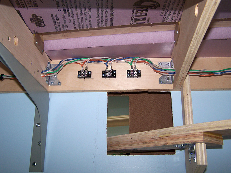
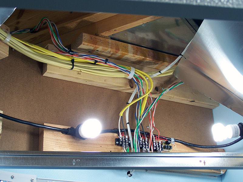
The LK&O has power! I have completed installation of three individual power buses around the layout – track power, control power, and accessory power. The track bus and its power supply delivers 17.1V DC at a maximum current of 7A. The diodes of the occupancy detectors effectively drop the voltage to 15V at the rails. Ideal voltage for the Rail Pro decoders in the locomotives. The control bus is for all solid state electronics on the layout and is separate from the other supplies so as to keep electrical noise to a minimum on the bus. The control supply is 12V and current limited to 10A. Lastly, the accessory bus is for everything other than the trains and the controls. All the motors, solenoids, light bulbs, LEDs, and whatever else will be on this bus. It is 12V DC and current limited to 10A with the option to raise to 20A if needed.
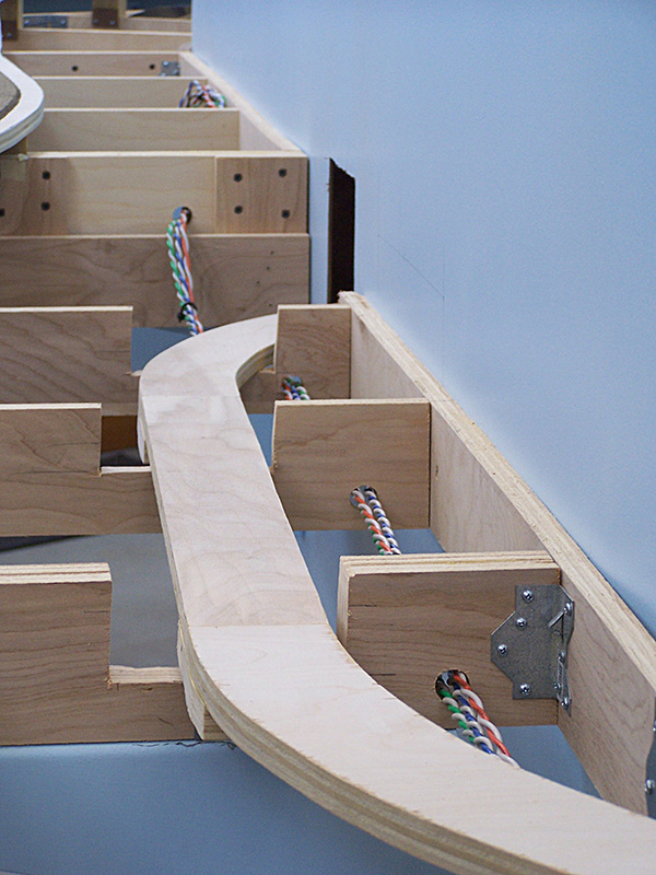
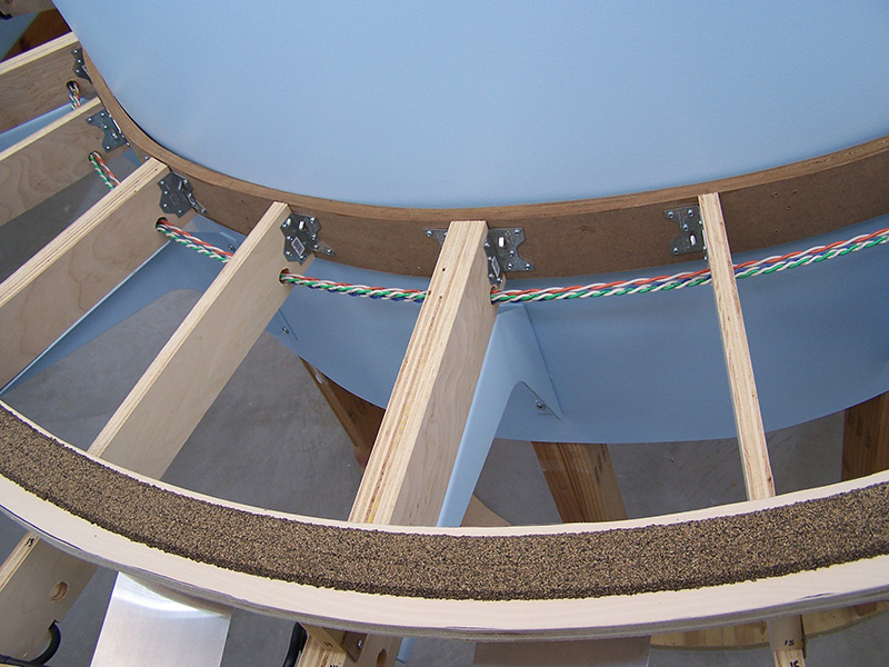
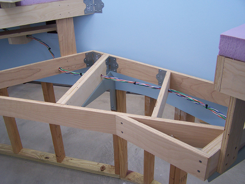
The bus routing resembles a lollipop with the stick being the wire run from the power supplies to the fascia panel and the benchwork wiring being a big loop from the fascia panel. This arrangement results in two paths to any one power point thus reducing the voltage drop across the long run of wiring. As a test, I hooked up an automotive halogen headlight to the power point furthest from the fascia panel. The current draw of the headlamp was 4.6A which is way more load than any one section of track will ever see. The voltage reading with the lamp off was 15V. With the lamp on the voltage was 14.2V. A voltage drop of only 0.8V isn’t bad at all considering the load was almost 100′ away from the power supply. I’m satisfied with that.
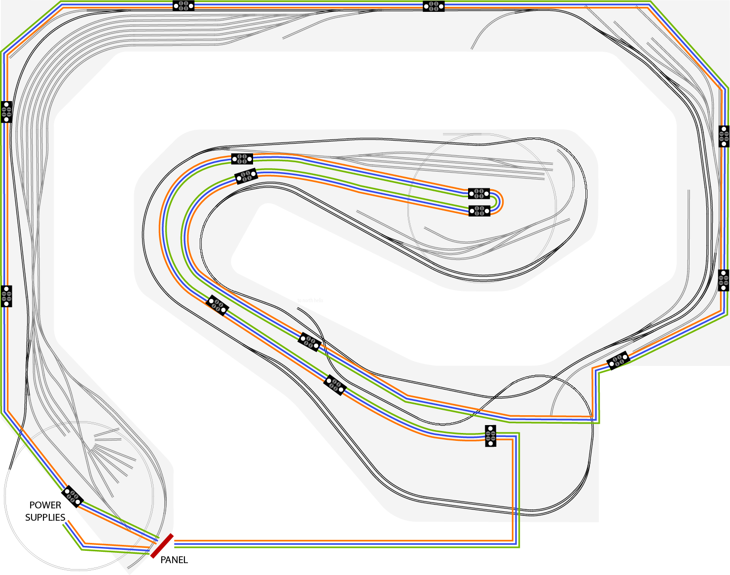
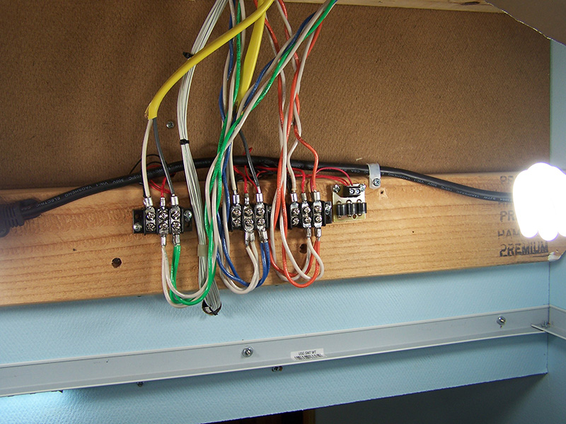
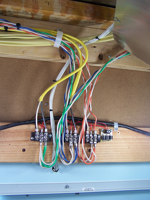
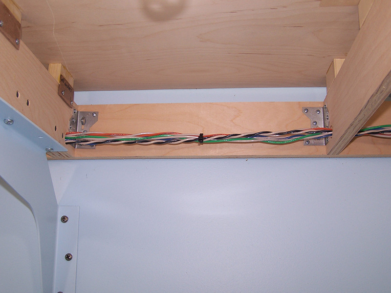
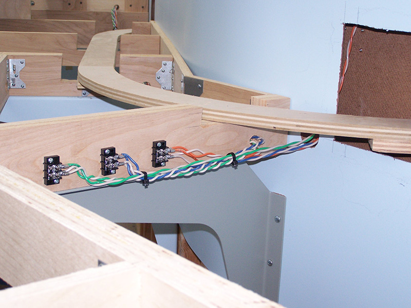
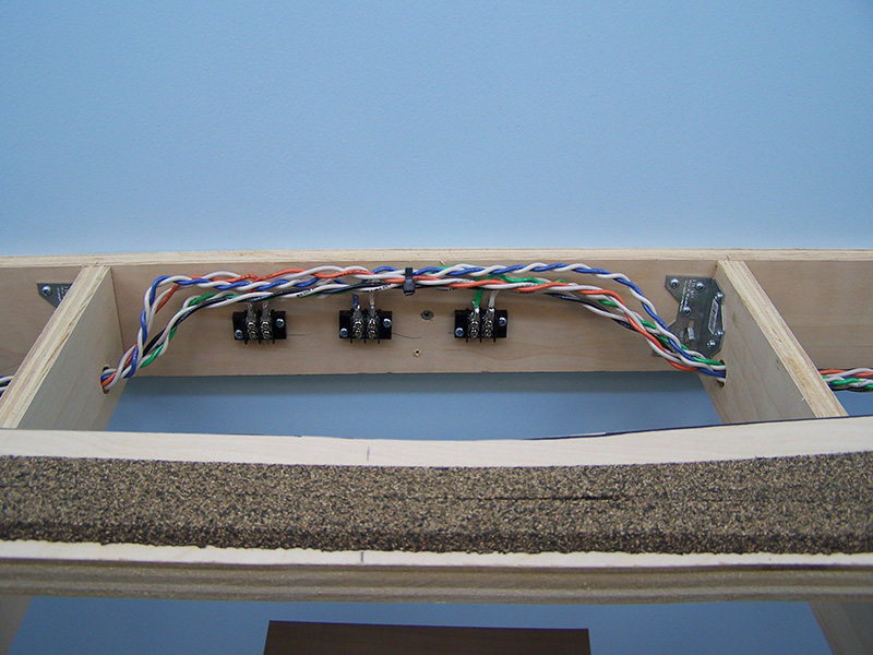
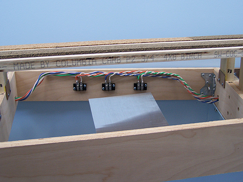
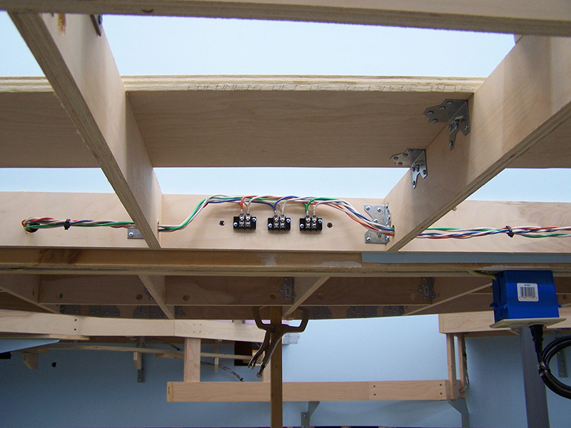
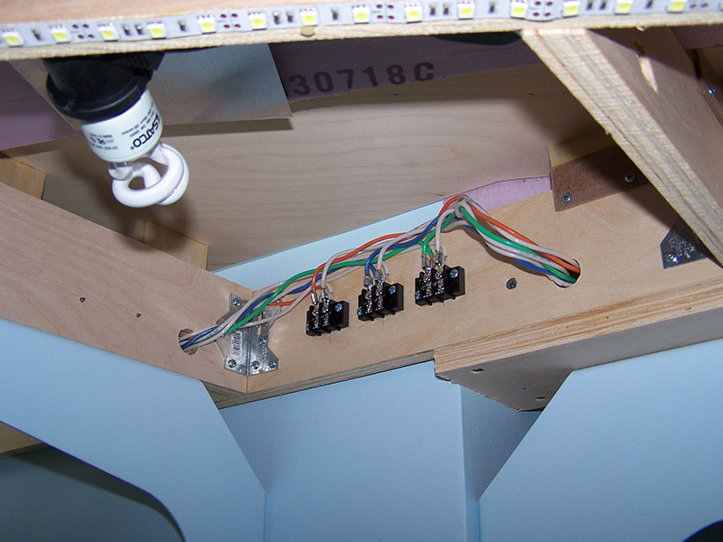
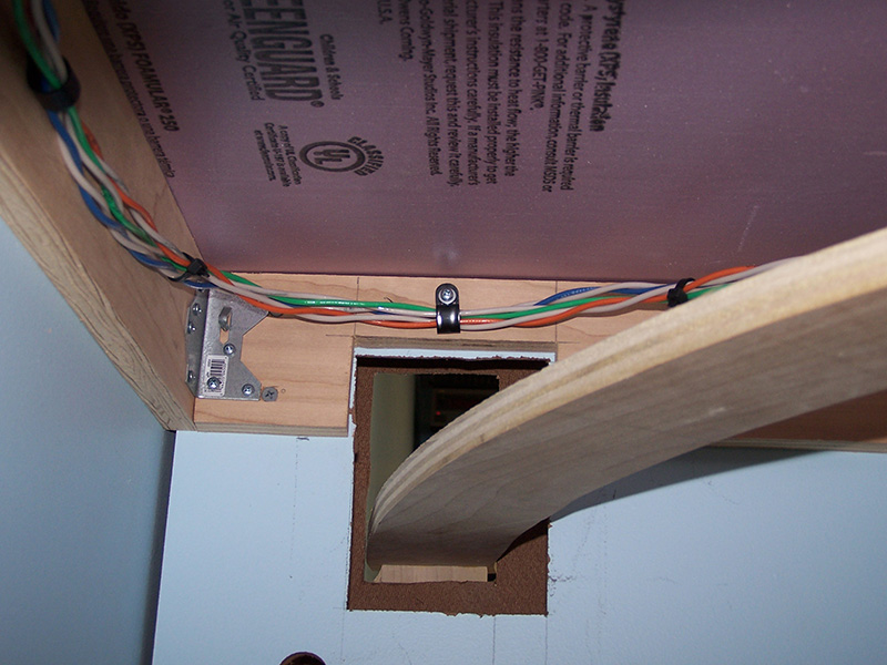
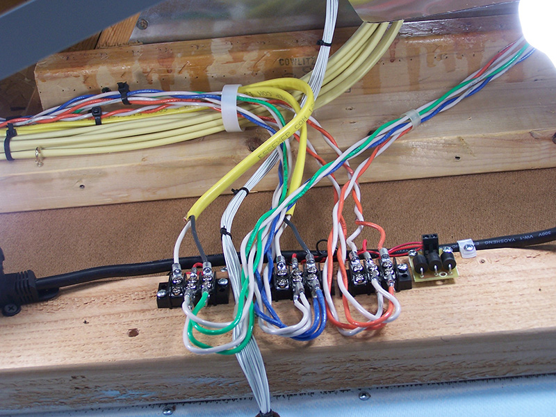
All three buses are 12 AWG solid THHN wire. White is used as return for each. Track power is orange, control power is blue, accessory power is green. The colors were selected to match the Cat 3 wire I am using for the hookups and rail feeders. Pulling a bundle of six 12 ga. wires through the benchwork was not a lot of fun. Required a good bit of grunt at times. Speaking of not a lot of fun, overhead soldering of the ring terminals was not especially delightful either. But all is done now and it works well.
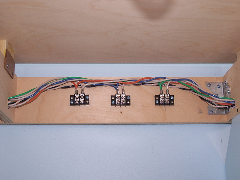
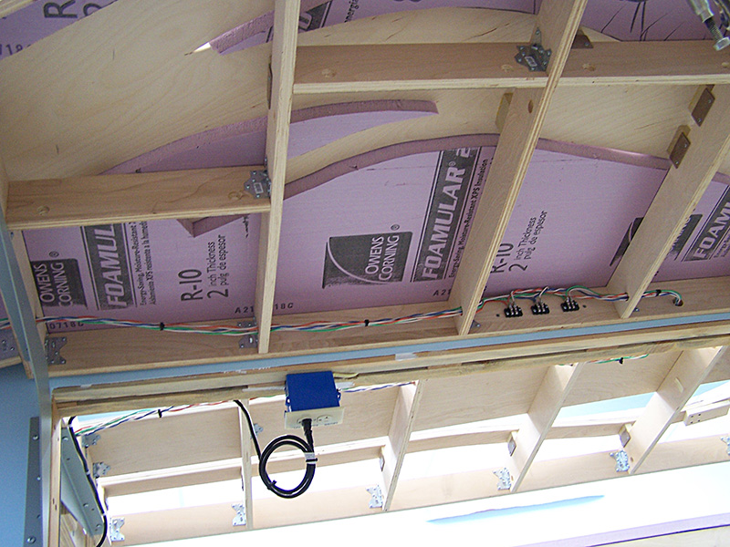
One little re-do…. the control panel. The stain came out too dark. 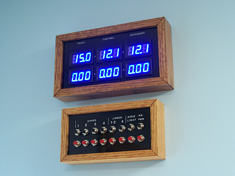 At first I didn’t think it was too far off but the more I live with it the more it bothers me. Since this photo was taken I have pulled the panel down, disassembled it, and sanded off the finish. It is in the process of being re-stained as I write this. I know what I did wrong. My usual process for staining to match the honey oak trim in the house is one coat of golden oak stain followed by two coats of golden pecan. I should have skipped the golden oak step on this panel because the oak was already sort of dark. Oh well, no big deal.
The layout has ingested another 950′ of wire. If you are wondering why copper futures are so high……. 🙂
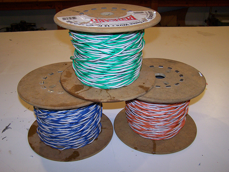
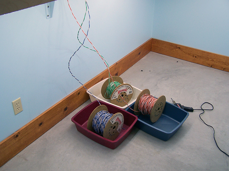
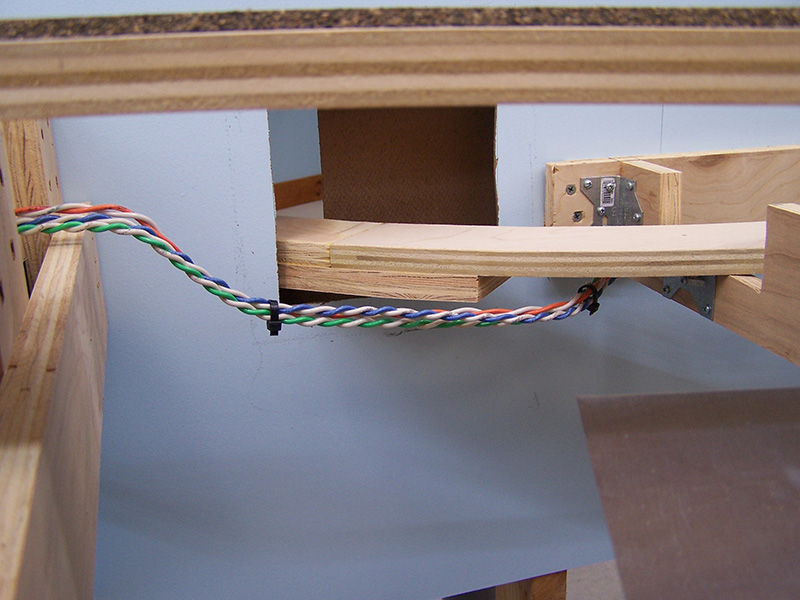
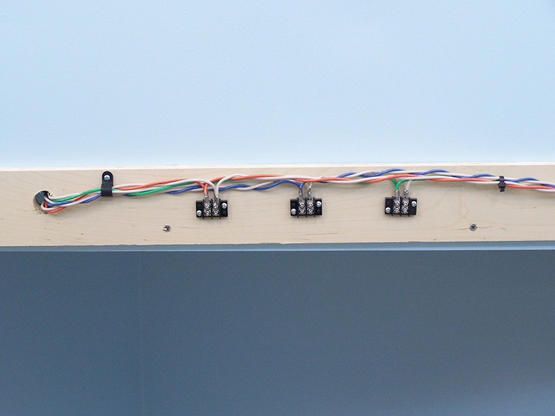

Alan, I noticed that your rolls of 12 ga. wire have magically become rolls of 12 ga. twisted pairs. Is this just for convenience of pulling or is it for interference rejection? Keep up the great work and thanks for providing a primer for many of us who are following your efforts!
You are correct. The twisted pairs reduce RFI and cross-talk between the buses. They also create a more constant impedance over the length of the run.
http://www.eeweb.com/toolbox/twisted-pair