Happy New Year! 2016 is here marking 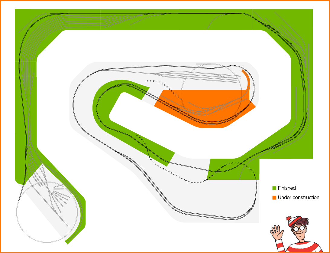 the beginning of the 6th year in my model railroad adventure. And what better way to celebrate than having the railroad complete through our little neck of the woods – Lapeer MI. At least a portion of Lapeer. A very small portion actually. OK make it a teeny tiny bit of Lapeer. The Saginaw St. grade crossing area to be specific. But at least the railroad is in Lapeer!
Some time off work for the holidays and a very understanding wife allowed me to make fairly rapid progress on the module. How about a run-through of the build process?
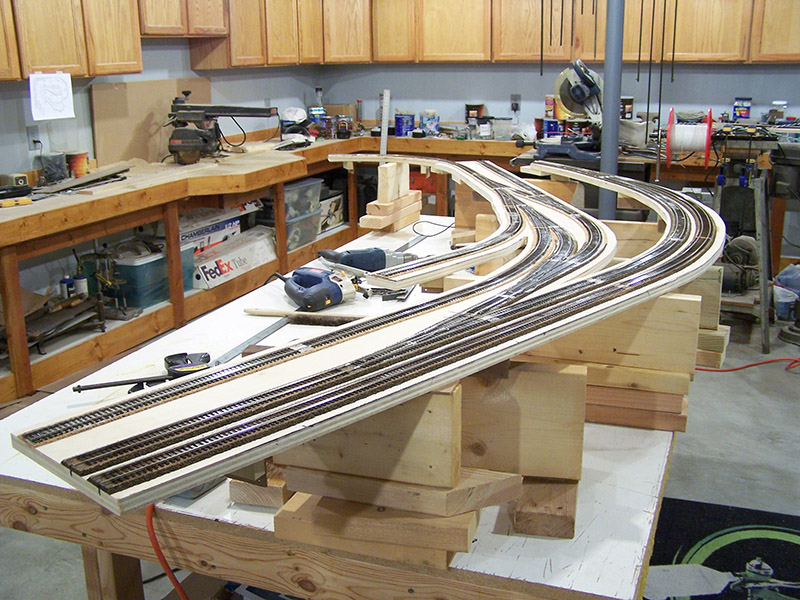
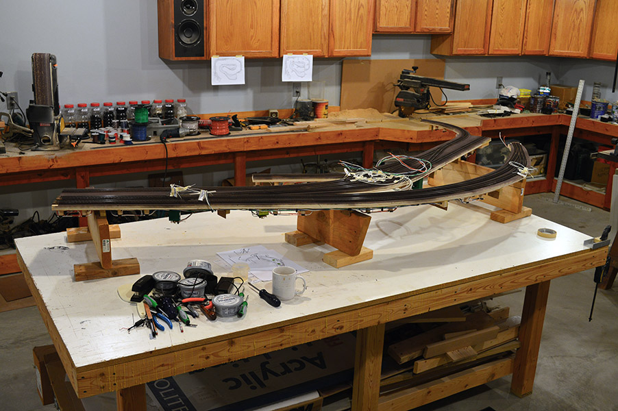
To get started the module is removed from the benchwork and hauled to the workbench:
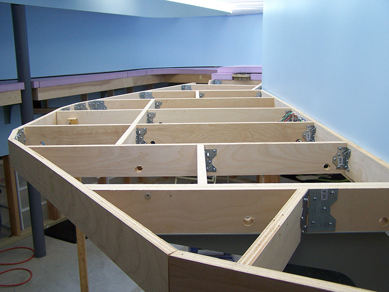
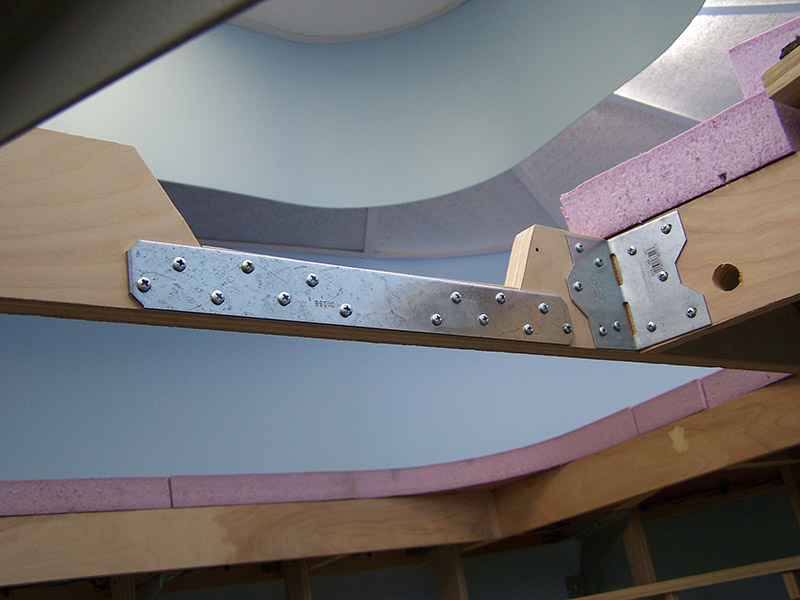
While the benchwork was open I took the opportunity to cut the relief for the river. A metal strap was added to the backside to maintain benchwork strength.
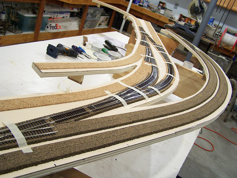
On the workbench the first step is to position the key track components. The throwbar positions are marked, track removed, and Tortoise slots cut:
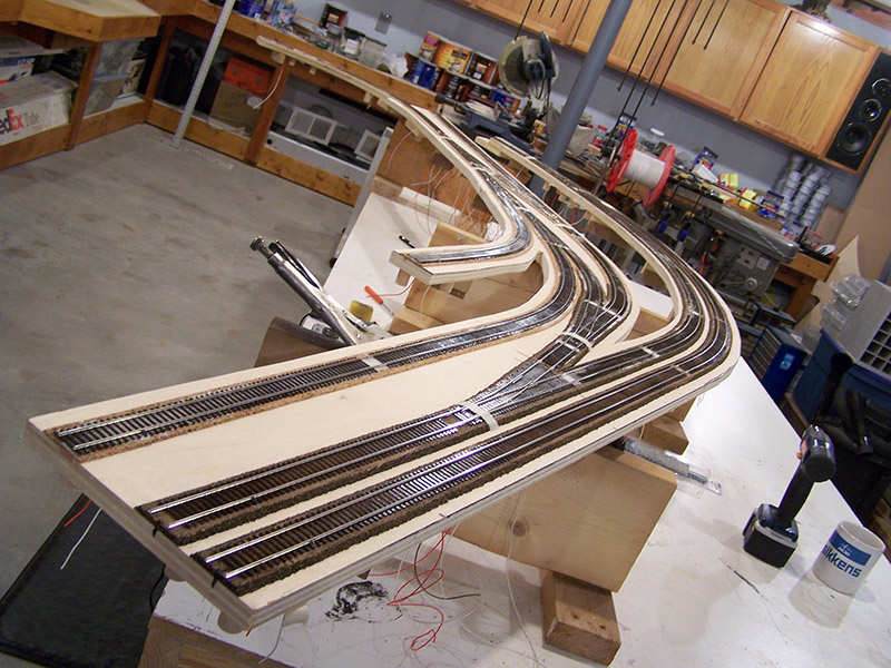
With Tortoise slots cut, the key track is caulked in place:
Remaining track caulked in place:
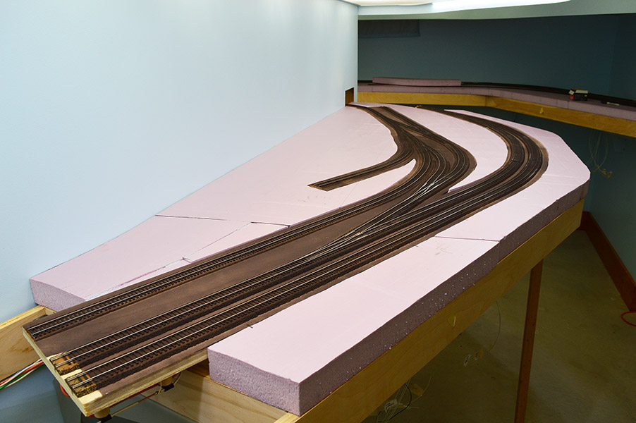
After several gluing sessions, each with an overnight dry, all track is caulked in place and rail joiners are soldered:
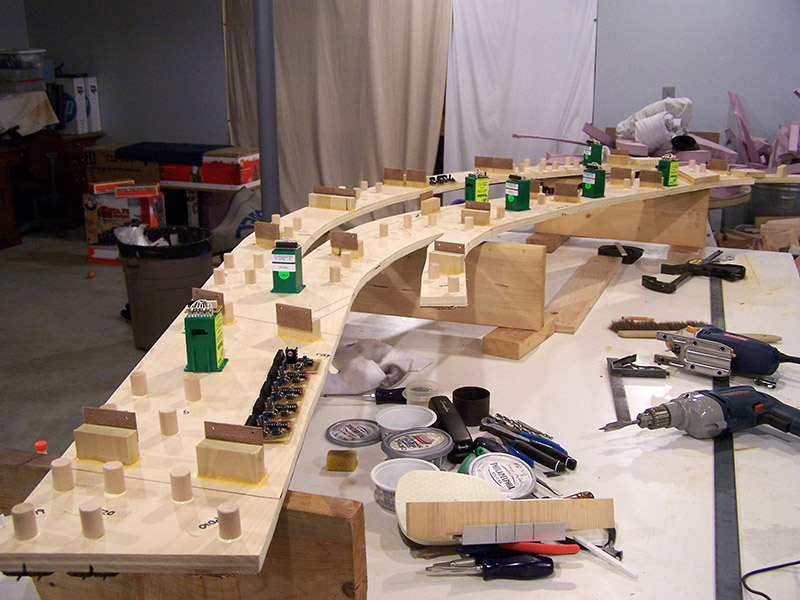
With the module flipped over, glue fillets are applied to risers. Tortoises, circuit breakers, and occupancy detectors are positioned and marked (but not mounted yet). Buss connection positions are determined and telephone poles glued:
With buss connection locations determined, the module is flipped back right side up. Feeder holes drilled, feeders dropped.
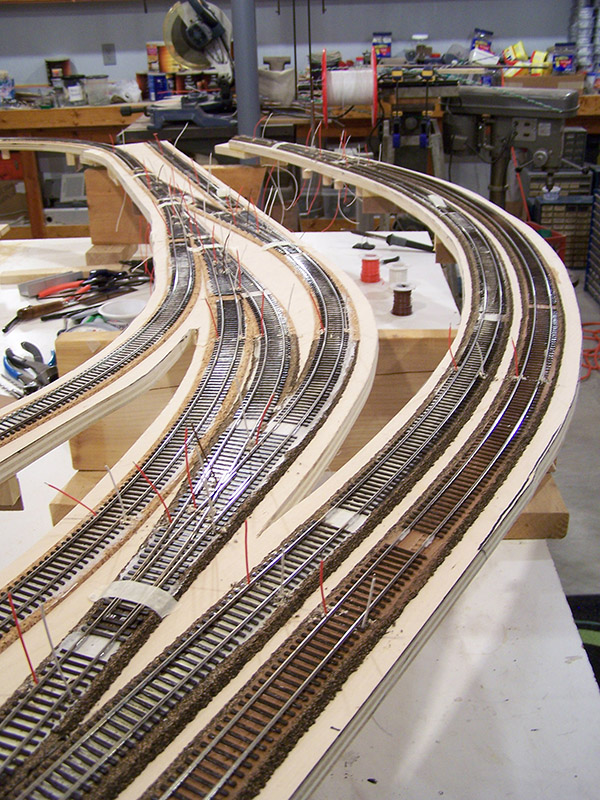
Feeders are soldered to the rails. Point rails on switches are taped into midway position:
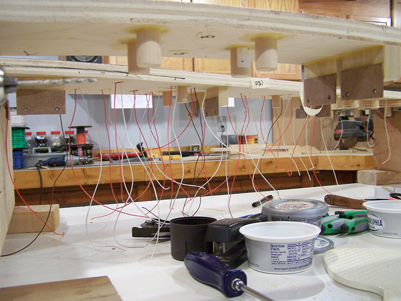
A view from below with feeders dropped:
With the module on its backside once again the time consuming part starts – wiring. I start by deciding the route the power bus lines will follow for the length of the module. The route is my best guess at one that will minimize wire congestion in any one place, not crowd Tortoise machines, and minimize wire run length. Sometimes I get it just right, other times not so much as the finished installation bears out. The installation order goes something like this:
- Tortoise machine mountings
- Circuit breakers, occupancy detectors, and voltage droppers mounting
- Bus bar mounting (if used)
- Track buses installed (orange/white 12 AWG)
- Feeders connected (orange/white 24 AWG)
- Accessory bus installed (green/white 12 AWG)
- Control bus installed (blue/white 12 AWG)
- Tortoise track power and frog connections made (orange/white/brown 24 AWG)
- Tortoise accessory power connections made (green/white 24 AWG)
- Occupancy detector power connections made (blue/white 24 AWG)
- Tortoise fascia panel leads routed – position LED and panel switch (white 22 AWG)
- Circuit breaker fascia panel leads routed – fault LED (white 22 AWG)
- Tidy up everything with nylon cable clamps and wire ties
- Apply labels
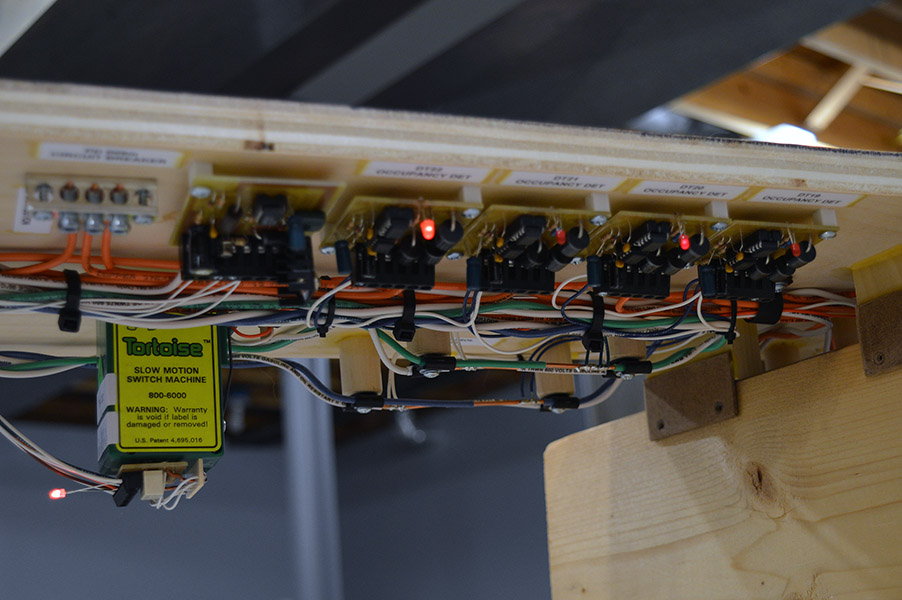
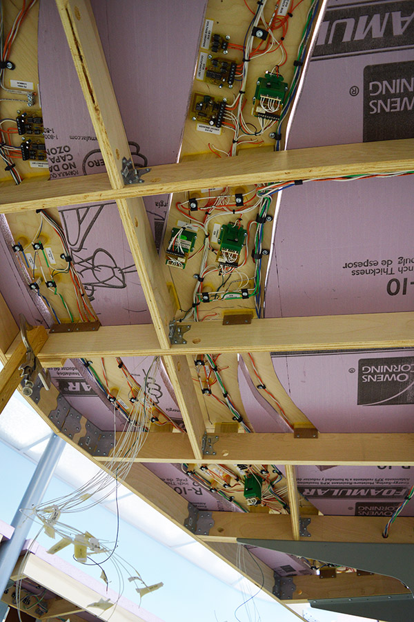
The end result:
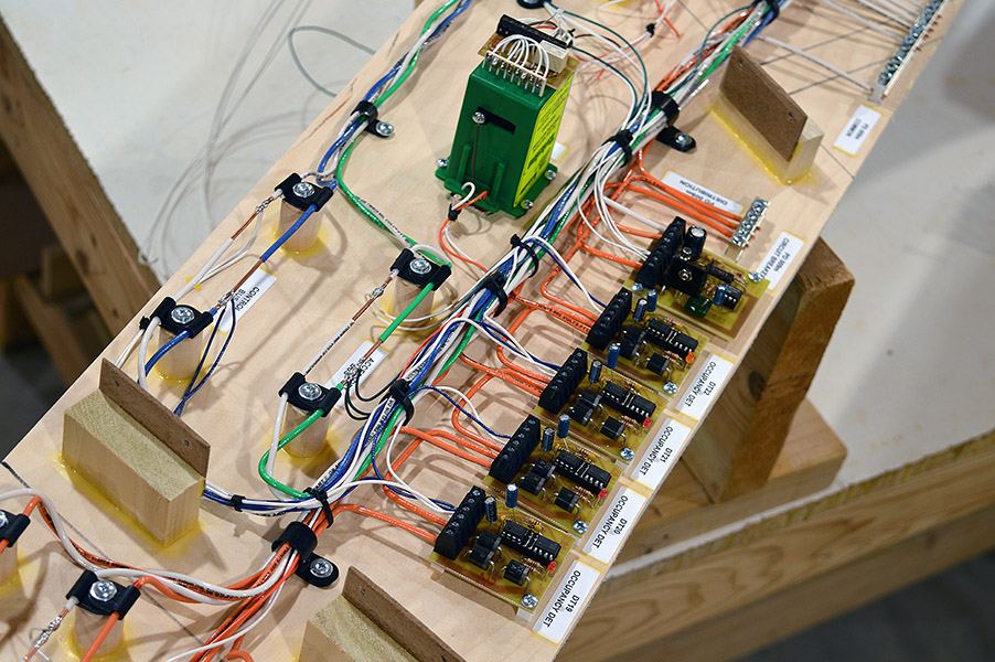
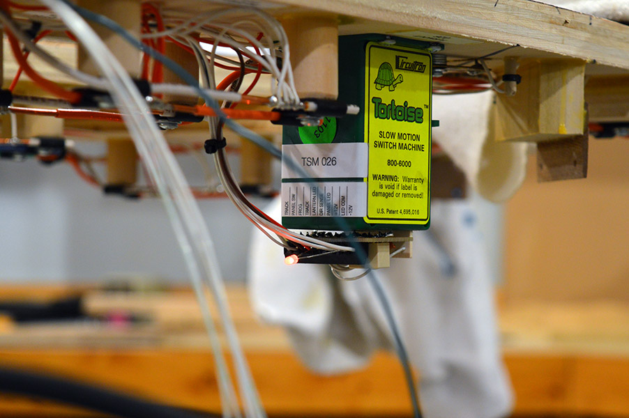
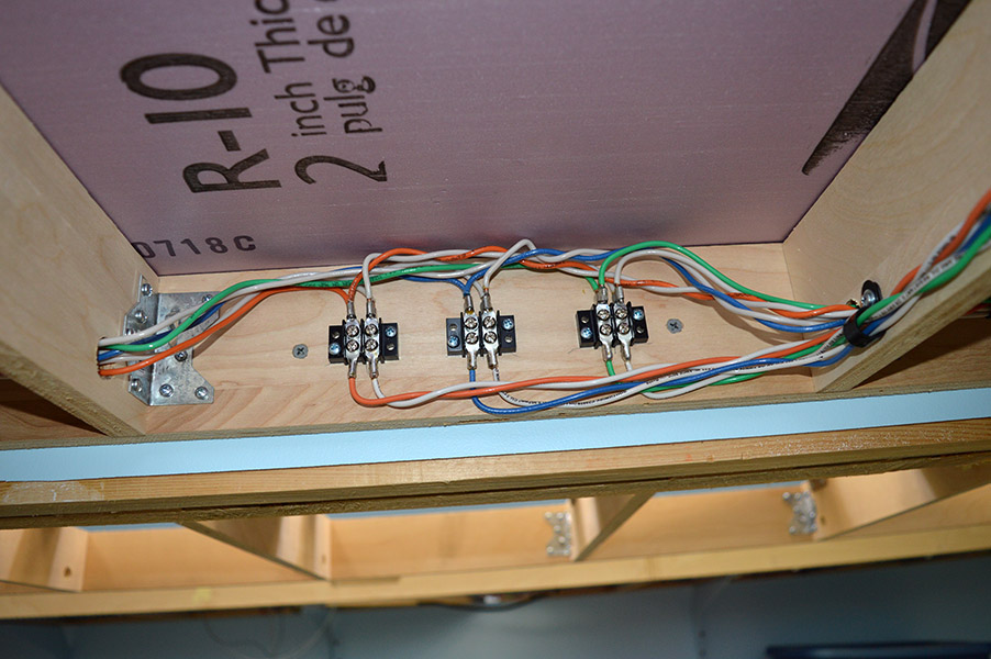
A closer view shows an example of all components – a circuit breaker, four occupancy detectors, a bus bar, Tortoise wiring including point rail wires, accessory bus, and control bus:
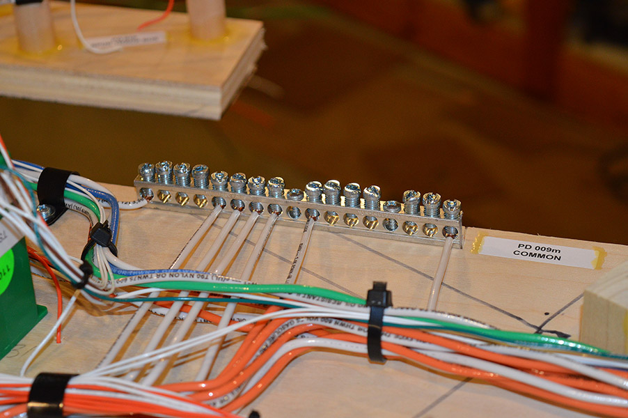
The bus bar for connecting all of the neutral track bus leads was so convenient on a previous module that I used another one on module #9:
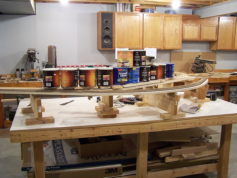
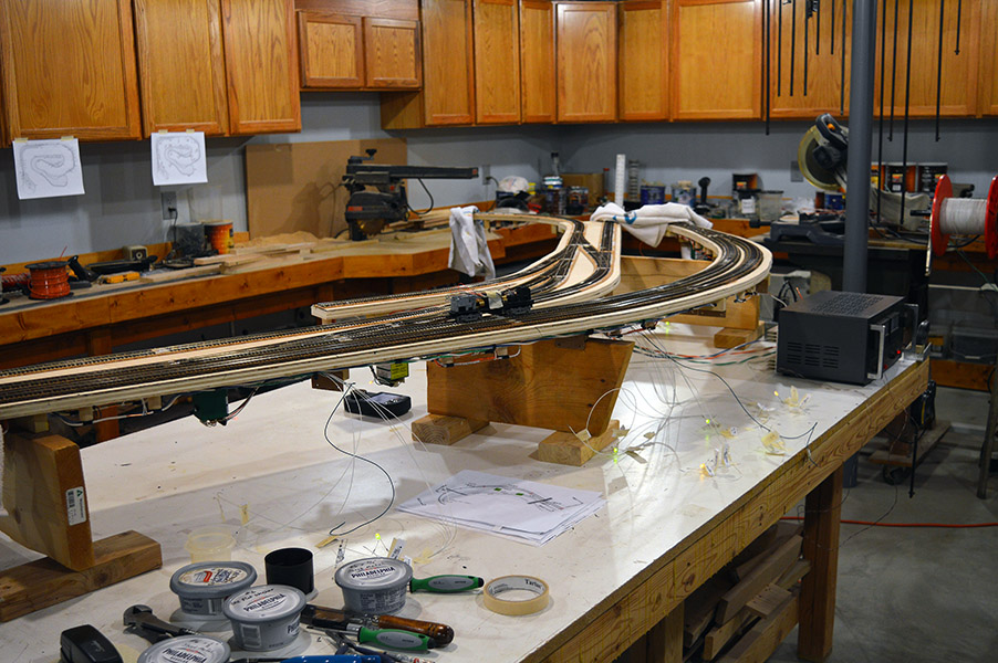
After all the wiring is complete it is time to flip the module upright and begin testing. Fascia LED stand-ins are temporarily wired:
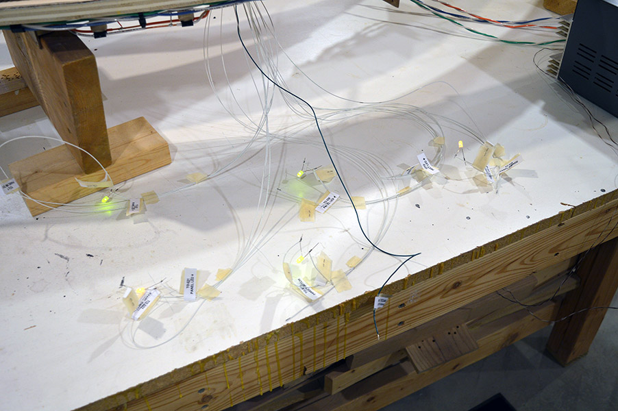
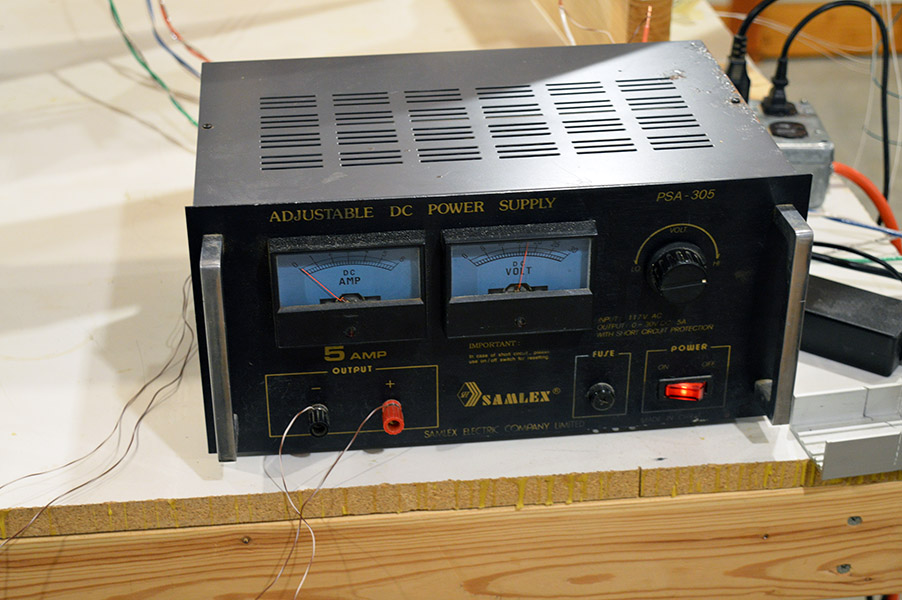
I use my bench power supply for rail power (17v dropped to 15v by detectors). A 12v wall wart powers the accessory and control buses:
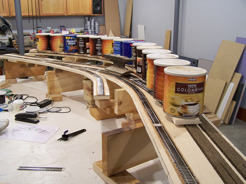
Tortoise machines are tested for free and complete movement, tension on the points, and correct operation of LED indicators:
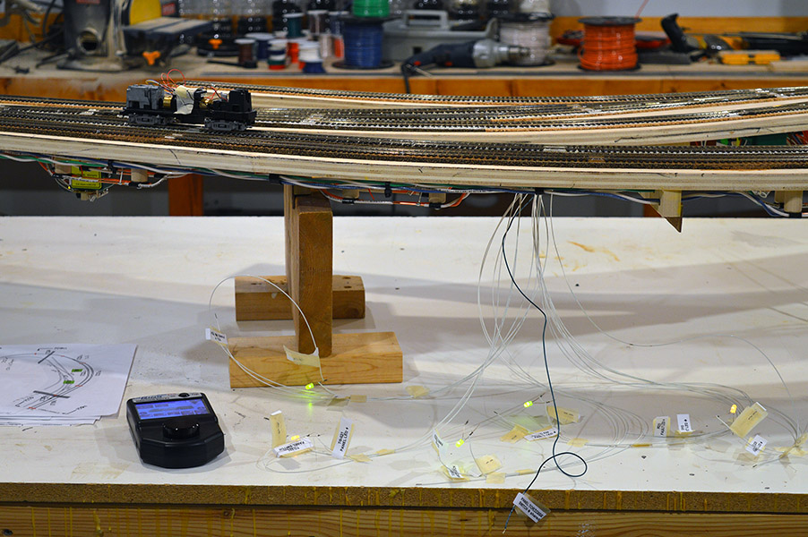
My testing mule, an Atlas H16-44 sans body shell, confirms proper operation of all occupancy detectors as well as track performance. Depending on the track arrangement I sometimes string a few cars together and shove them over the trackwork too:
Satisfied everything is working properly, I mask off the bottom edge of the sub-roadbed with 2″ masking tape and cover the workbench with a couple old bed sheets to protect from overspray. The track is lightly painted camo brown and the rail heads wiped clean with a lacquer thinner rag. Remove the masking and coiling the fascia leads makes the module ready for re-installation:
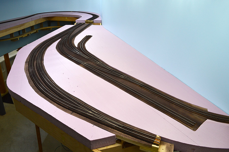
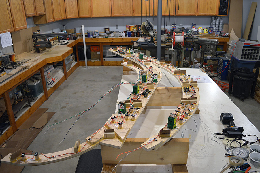
With the gracious help of my wife the module is carried into the train room and hoisted into position:
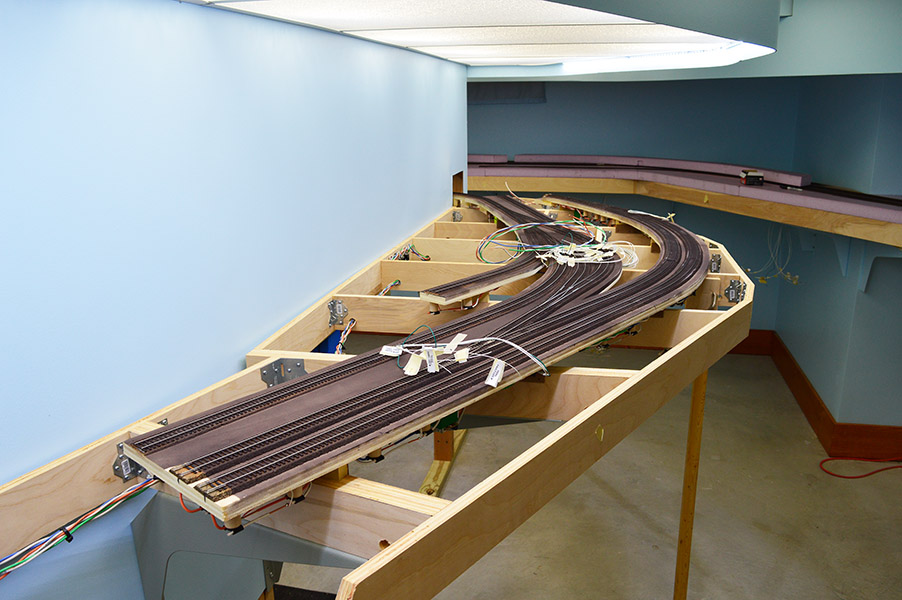
All the modules have fit real nice when set back onto the benchwork. The Lapeer module was no exception. The nice fit is due to the arrangement of the risers and their respective attachment flanges. There is only one position on the benchwork where all of the module riser flanges will drop into position. A little nudge here, a little nudge there, and all of a sudden.. thunk, the module drops into place. Inserting the riser screws and replacing the foam finishes the placement:
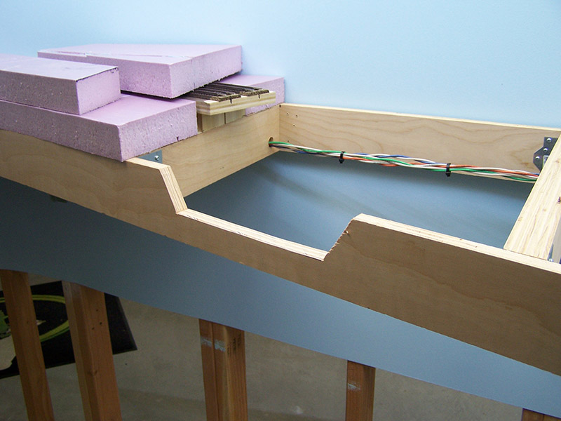
All that is left is to connect the bus leads to the “grid”:
I love how the entire electrical system is self-contained on the module leaving the benchwork free and clear for whatever may come:
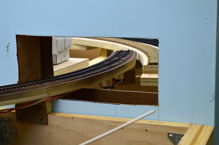
An interesting note. Normally there is no occupancy detection on industry spur tracks but on module #9 there is one spot that is detected. It is the end of the track that disappears into the backdrop. Once scenery is in place an engineer won’t be able to see when his locomotive or cars being switched reach the end of the line. The end is inside a mountain on the Maryland side of the layout! The extra track length was necessary to facilitate switching Lapeer. The prototype spur extends for quite some distance servicing other industries. I did not have room for the full spur so I stole some hidden space from the Maryland side to make the spur as long as possible. The last six inches of the track is a separate circuit with an occupancy detector. I don’t know just yet what kind of signal I will have, be it a buzzer, a light, or something else, but there will be a signal to tell the engineer STOP NOW:
Well, there you have it. Building the Lapeer module from start to finish. I had a blast!
Wishing everyone a healthy and prosperous 2016,
Alan

Alan, Excellent post! I especially appreciate your taking the time to list your installation step process. Your bench work and track laying is very elegant. Keep up the great work. The best in this new year.
Thanks David.
Hi Alan
thank you very much for your descriptive post. I really appreciate your work as an inspiration during construction of my own model railroad.
best happy new year wishes from Switzerland, Adrian
The LK&O must look flat and boring to someone from Switzerland with all its dramatic mountain scenery. Glad to have you following along Adrian.