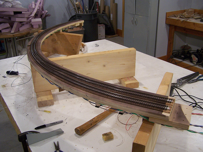
This module was super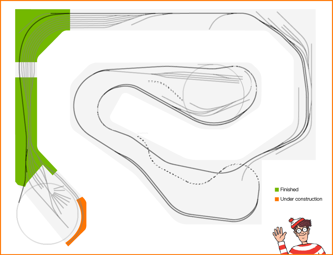 easy and fast to construct. There isn’t much to it. This is my representation of the real Spur #4 on the AC&Y. It was the line that went from Brittain Yard to the General Tire rubber shop and then on to Goodyear Plant 1. It was also the interchange with the Akron Barberton Belt RR. Appearing as a siding on spur 4 within yard limits and right next to
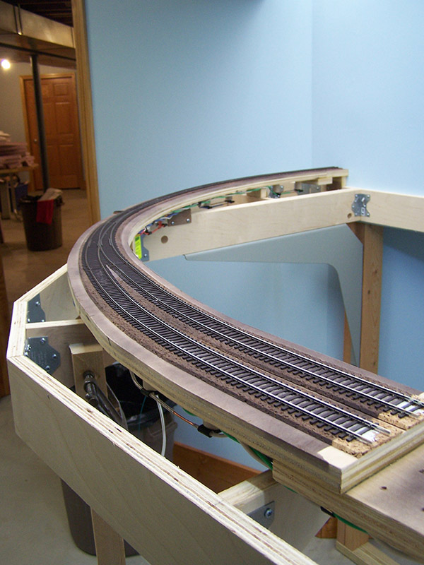 the roundhouse was the caboose track. That is the key function I represent on my railroad. Module #3 is the west end of my caboose track. The “B” plate between module #1 and this module extends the length of the siding section that holds cabooses.
While on the real AC&Y spur #4 served only the above two purposes, on my railroad it serves yet another. It is the primary yard lead. The AC&Y used the main for a lead to switch the yard. It worked for them due to the low volume of traffic. My model railroad has no where enough mainline length to keep trains out for half a day. So, I can’t use the main as a lead without severely clogging up everything. Spur 4 works as a lead without modifying the track plan. Sweet! A functional lead while retaining the track arrangement of the real Brittain Yard.
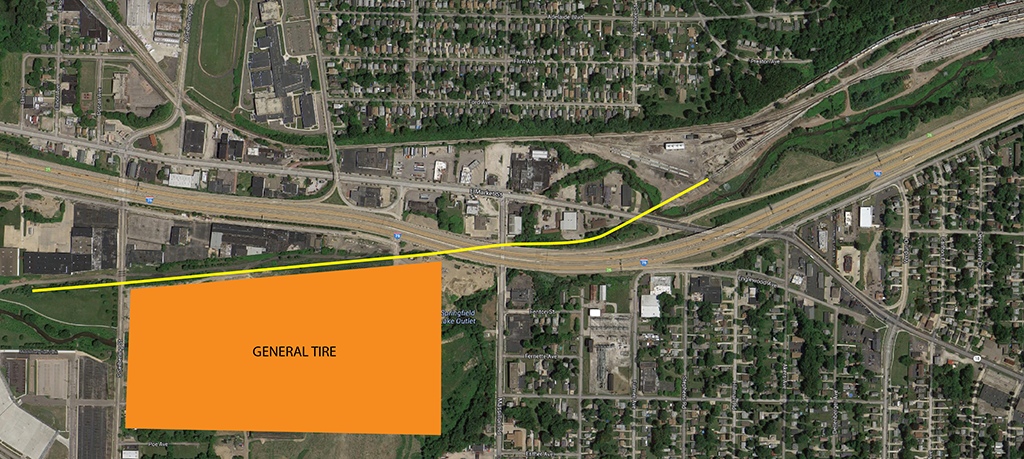
Below is a graphic showing the original location of spur 4 (partial). The line extended west for a mile past where my yellow line stops. The tracks are of course long gone from Google maps now. Click for a bigger view.
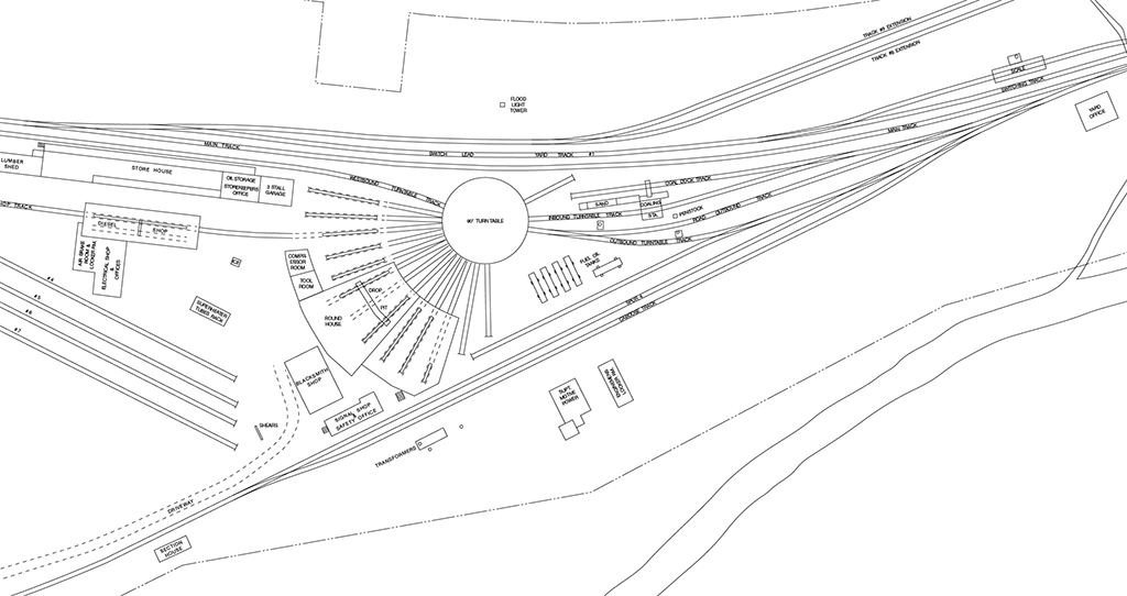
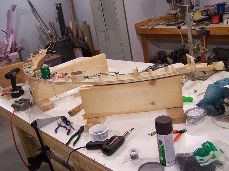
Below is a site plan for Brittain Yard engine service facilities that shows spur 4 and the caboose track. This area is accurately modeled on my railroad other than my spur 4 is curved instead of straight. A modification required by my room configuration.
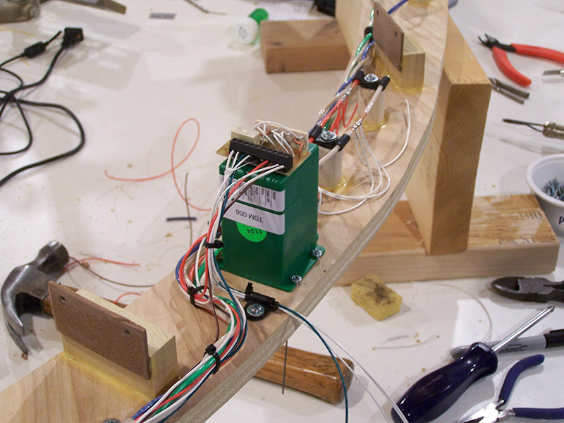
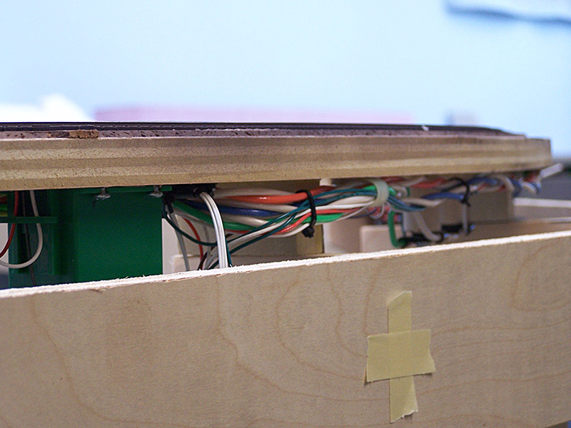
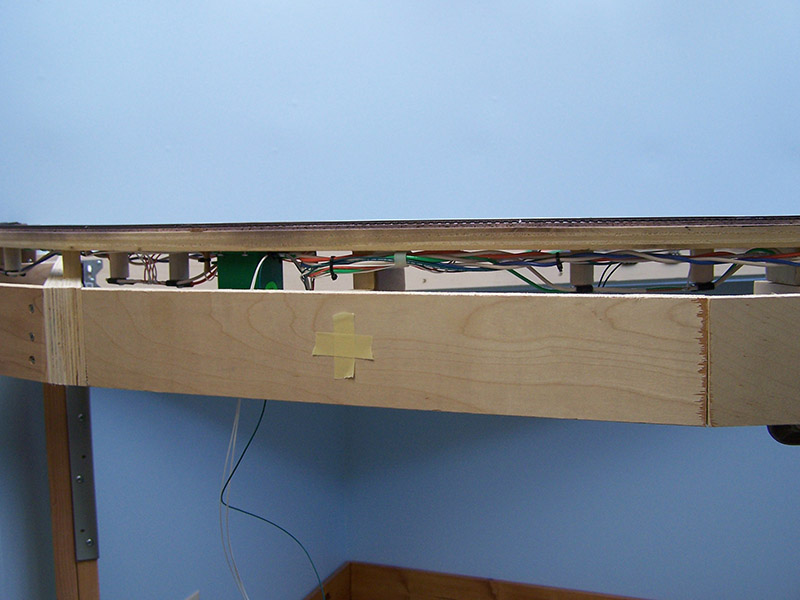
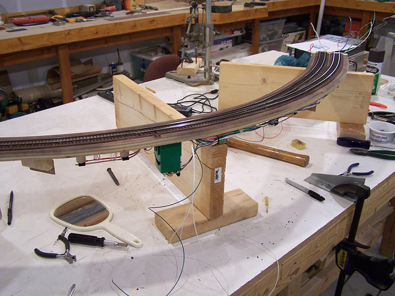
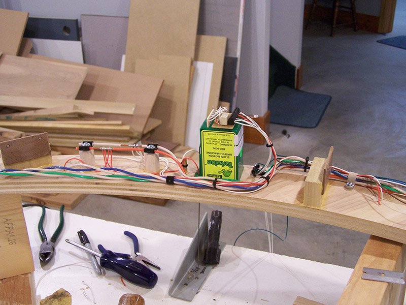
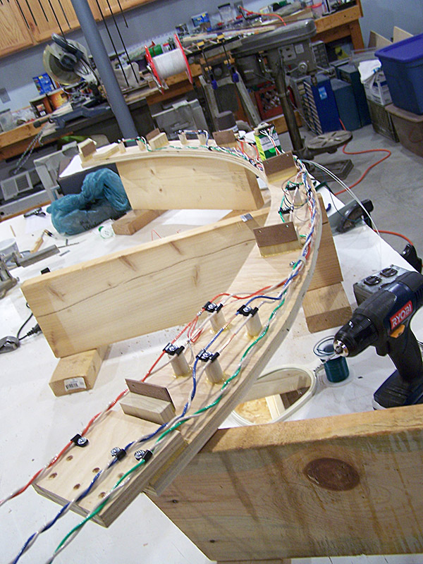
With the sub-roadbed being so narrow the wiring got a bit cramped around the Tortoise machine. Glad there wasn’t much wiring needed or it could have gotten very tight under there.
So much for the easy modules. Next comes another module loaded with switch machines. Module #4 is up next.


Alan, I noticed on the track plan that the track on this module extends through the wall and becomes a long hidden spur. Have you decided to not continue through the back drop or is that the next step?
Rob,
Yes, I decided against the hidden section for several reasons. One, I would have to build some means of alerting the engineer he is nearing the end of track. A lot of infrastructure for not much more lead length. Second, the lead ending at the wall is longer than any classification track so as it is a whole class track can be pulled. Third, by not going through the backdrop I was able to move the lead out closer to the layout edge thus gaining some space between the lead and the helix hiding scenery that will eventually be in, what is now, the big gaping hole in the center. Lastly, the change allowed me to increase the helix diameter by about an inch. Every bit helps to keep the helix grade as low as possible.
Good eyes there buddy.
Alan,
Excellent workmanship and system design, it seems to be serving you well. I noticed a number of your Tortoise devices have LEDs inserted in to the terminal strip, others do not. Are these temporary and what is their purpose?
Yes, the LEDs you see on the Tortoise machines are temporary. They were required for testing purposes. They are stand-ins for the switchstand lanterns that will eventually be at the turnouts. The switchstand lantern LEDs are wired in series with the Tortoise motors so they must be present for the machines to work. Some were removed after testing if the clearance between Tortoise and benchwork crossmember was tight. Did not want to damage an LED while placing the module back on the benchwork. Those left in place are so that I may see the anode/cathode lead positioning on the terminal block when I connect the real switchstand lanterns.
Alan, your progress is looking great, I really like the way you are able to evolve your plan and make the little “tweeks” you are doing to it’ particularly in light of the fact that you hired a designer to help with your track plan.
Great work the wiring you are doing is top notch. I keep looking for some maker to come out with a version of the heavy duty but so far no soap. If released I sure hope it is Atlas as they do a nice job on FMs and their drives are fantastic. I am really looking forward to seeing your ring engineering system in action!
Alan – Have read your blog for awhile and can honestly say that there is someone, neater, more organized and more systematic than myself… wow… enjoy your thought process, design rigor and willingness to explore new methods of construction… looking forward to more.