Did you invest in copper futures? Well, you should have. I have bought so much copper wire in the past two months I surely boosted the copper market!
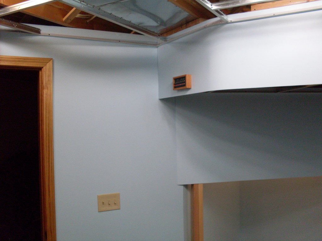
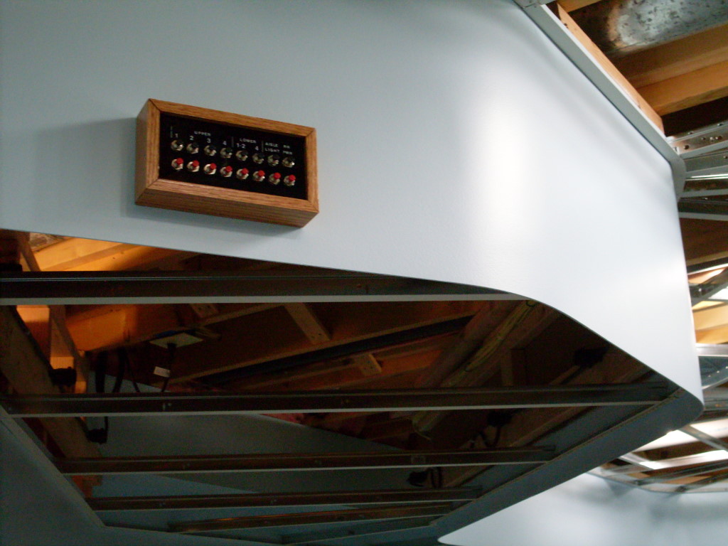
The LK&O lighting system is complete. I turned on the power for the first time this weekend and, believe it or not, everything worked as hoped. Ah, what a feeling to have something work first time out. The room lighting, layout lighting, and railroad power are now controlled by a small panel on the valance near the door. Walk in, flip the wall switches, and start pressing buttons. Sweet!
 Recall my dilemma was how to control all of the train room electrical from the wall switches without actually using the wall switch circuit to power everything. The wall switch circuit is only a single 15A circuit, not nearly enough capacity to power all my lights. My new arrangement accomplishes the task of controlling everything tied to three individual 20A circuits and a 15A circuit with the wall switches by using relays.
The Control Panel
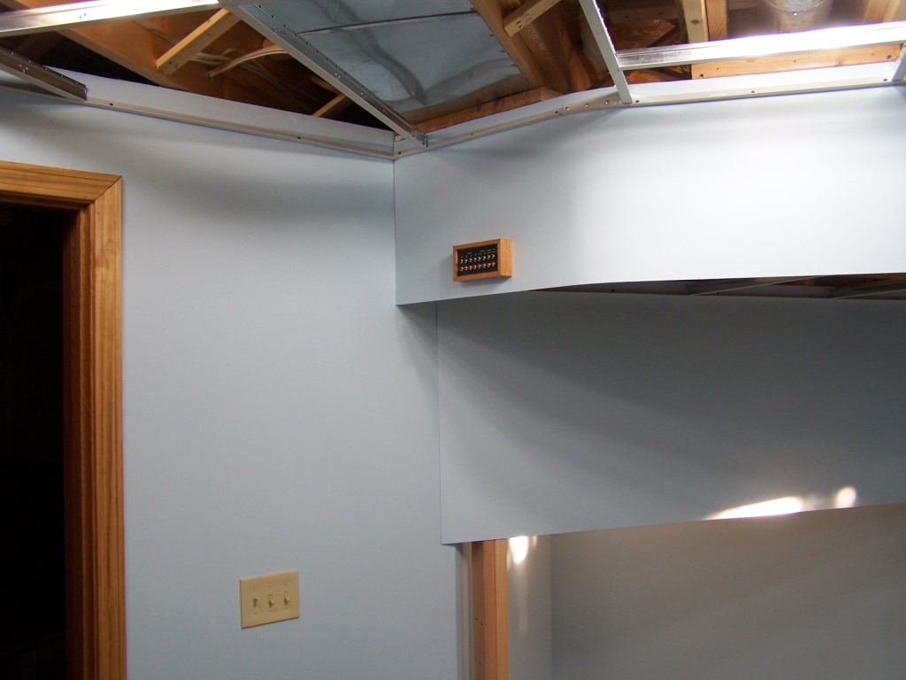
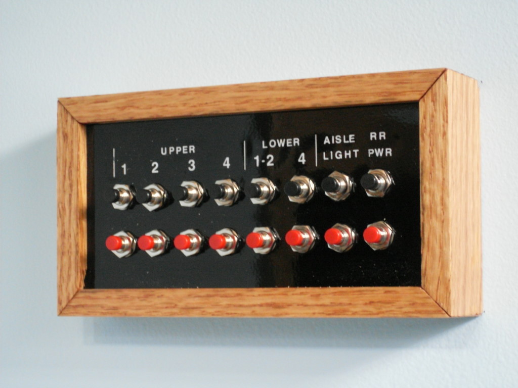
Momentary push button switches are mounted in a little wood and acrylic panel on the valance. The feed for the push buttons comes from the wall switches – SW1 room lights, SW2 layout lights, SW3 railroad power. Pressing a black button (normally open) supplies power to the corresponding relay(s). The DPST relays are wired so one set of contacts powers the relay coil when closed. This makes the relays act in a latching manner.  One press of the push button closes the relay and then the latching wiring arrangement keeps the relay energized after the push button is released. Pressing a red push button (normally closed) interrupts the wall switch power to the relay latching contacts thus opening the relay. The beauty of this arrangement is I can flip the three wall switches on the way out and be assured everything is powered down.
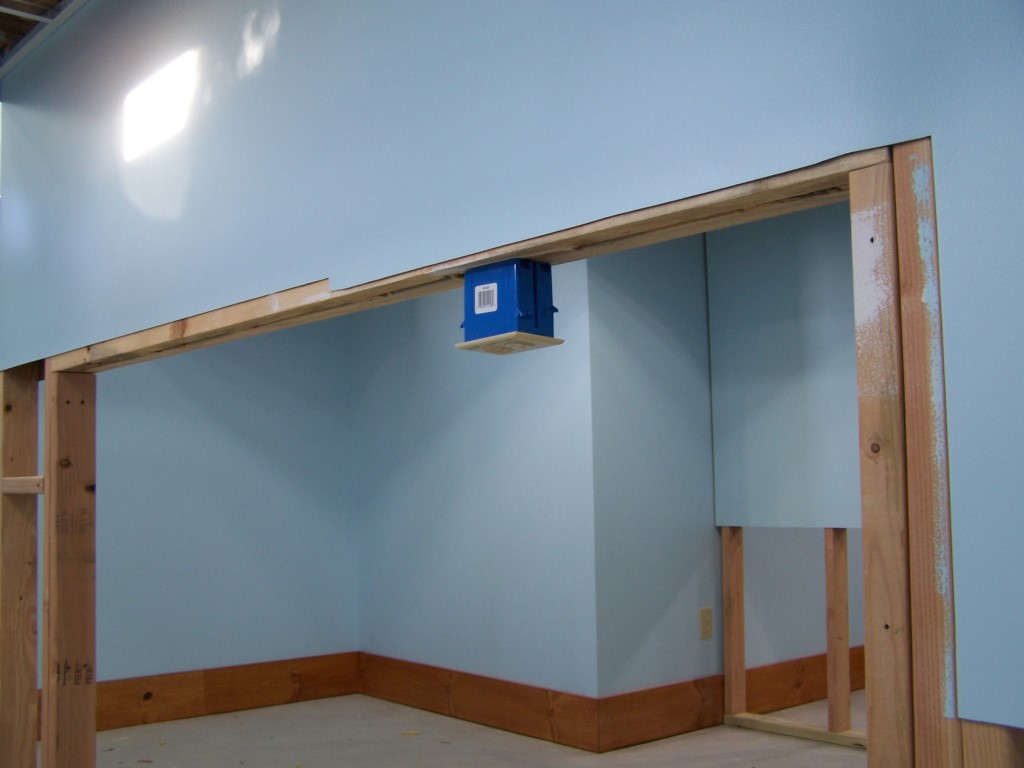
The panel is constructed from oak and acrylic. An 1/8″ wide, 3/16″ deep groove was routered in a 3/4″ x 2″ x 2′ piece of oak after which the pieces were miter cut on a radial arm saw. A coat of Golden Pecan stain and two coats of Minwax Polyurethane Satin completed the wood sides. The acrylic face is 1/8″ thick, drilled and painted black on the backside. Dry transfer letters were applied on the front with clear lacquer sprayed over to protect them and provide a smooth glossy finish. I find that spray paint does not like to flow out over dry transfer letters. To solve this I apply two very light coats of clear lacquer with plenty of flash time between coats. Then I follow with a flowing wet coat. After a day drying I then wet sand the surface flat with 600 grit sandpaper. Two more coats of clear are sprayed over the sanded surface. This process works well to get rid of the dry transfer letter wringing effect. Once the push buttons were soldered to lengths of wire they were installed in the panel. The oak sides were then placed with the acrylic sitting in the groove and a a little Gorilla glue placed on each miter face. Rubber bands were wrapped around the assembly to hold it tight while the glue dried. Finally, a 1″ wire exit hole was drilled in the lighting valance and the panel mounted with #6 x 3/4″ screws.
The Wiring
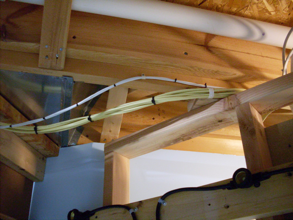
There is over 500′ of 12 ga Romex in the train room somewhere! I started with a partial roll of about 50′. Then I bought a 250′ roll. Then I bought another. Today I have a little 10′ piece left. It is no wonder why I went through so much wire. First I had to pull two circuits from the load center which is at the opposite end of the house. Our load center had one last remaining open breaker spot. I fitted a dual 20A breaker in the spot. Next, all of the wiring between the 12v power supplies and the LED strips is also 12 ga. This was done to minimize voltage drop so the LEDs are as bright as they are meant to be.
I learned something new while stringing wire. House wiring has insulation rated at 600v. I don’t know why but assume there is a good reason. My wiring for the push buttons is 115v AC so, following suit, I wanted those wires to have 600v insulation also. The relay coils are 115v so they draw very little current.  Something on the order of 0.07A. Because there are so many wires exiting the control panel and they carry so little current I wanted them to be a real small – 22AWG. Have you ever tried to find 22 gauge wire with 600 volt insulation? It can be found but don’t expect a deal. To my dismay I realized I was going to pay over $40 just for the short length of wire I needed if I purchased it from wire suppliers. Forget about finding this stuff at a big box store. Then eBay came to the rescue. I purchased a 2000′ roll (yes, 2000 feet!) of MIL spec TYCO Electronics premium stranded wire for $9.99. That same roll would have been hundreds of dollars at a wire supplier. I had enough to wire my control panel with 1,950 feet left over!
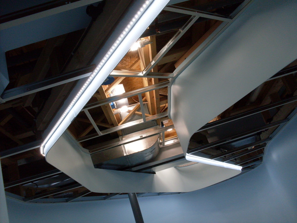
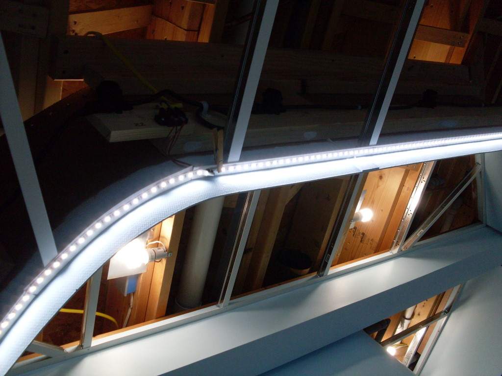
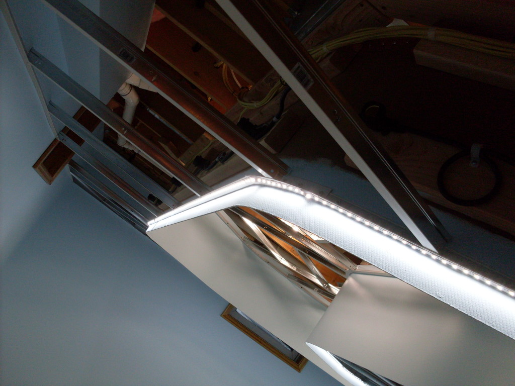
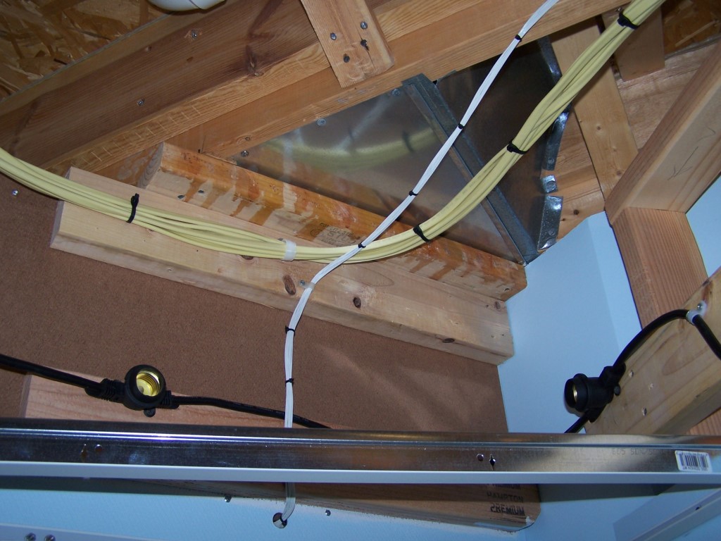
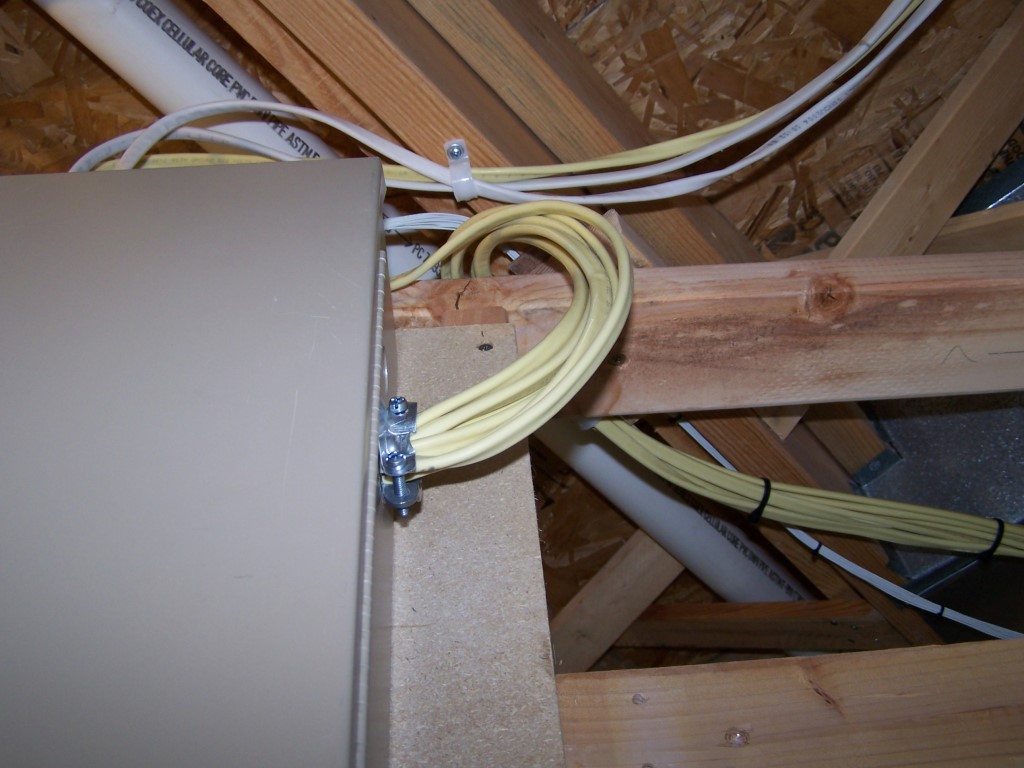
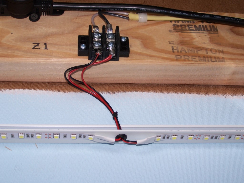
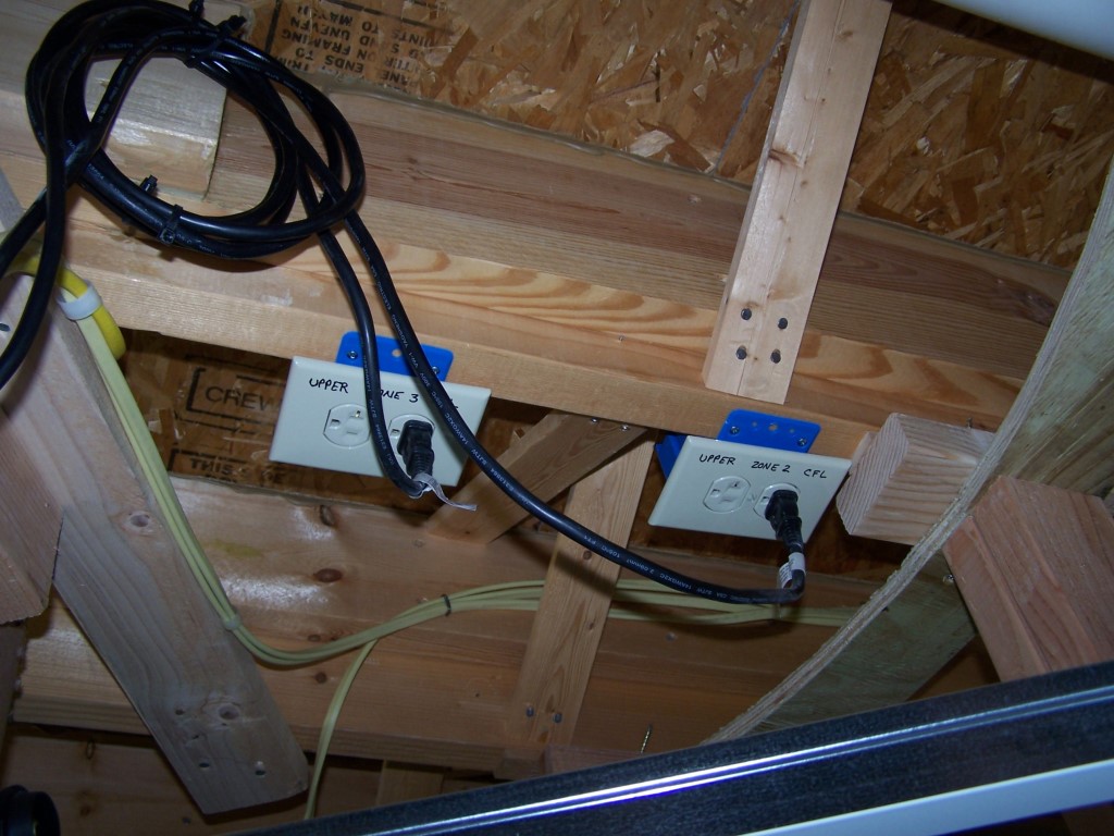
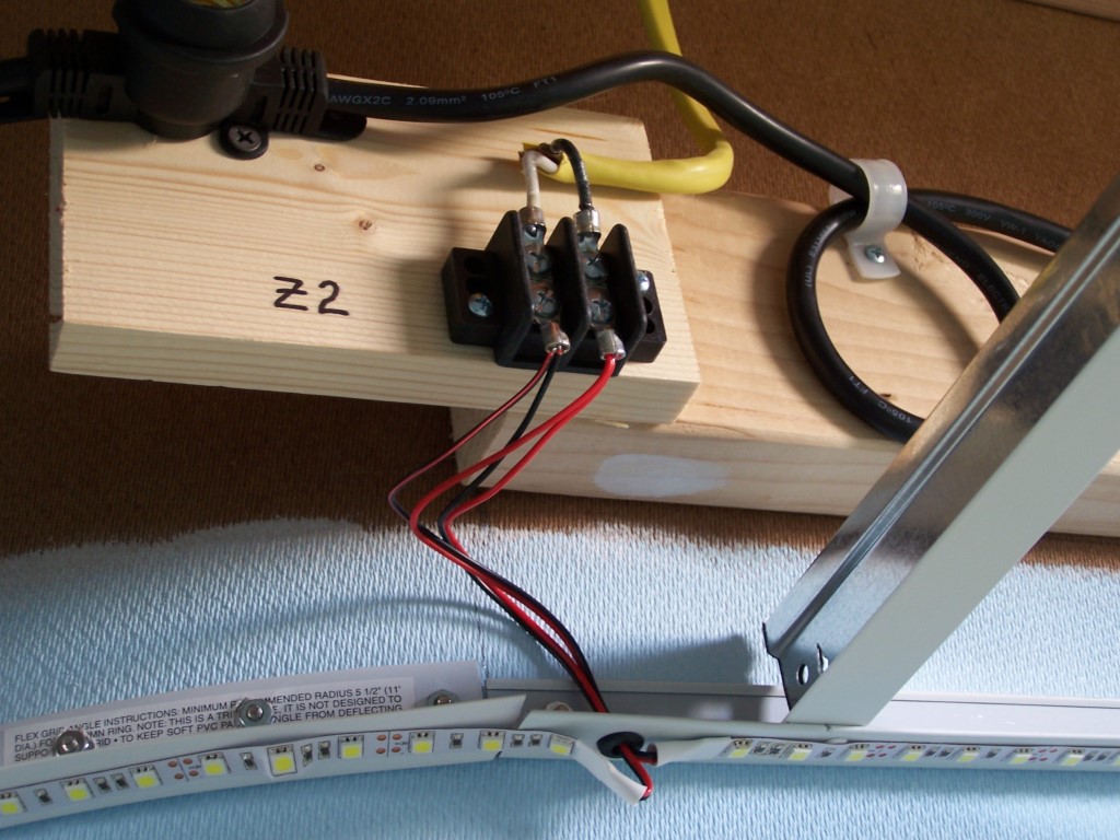
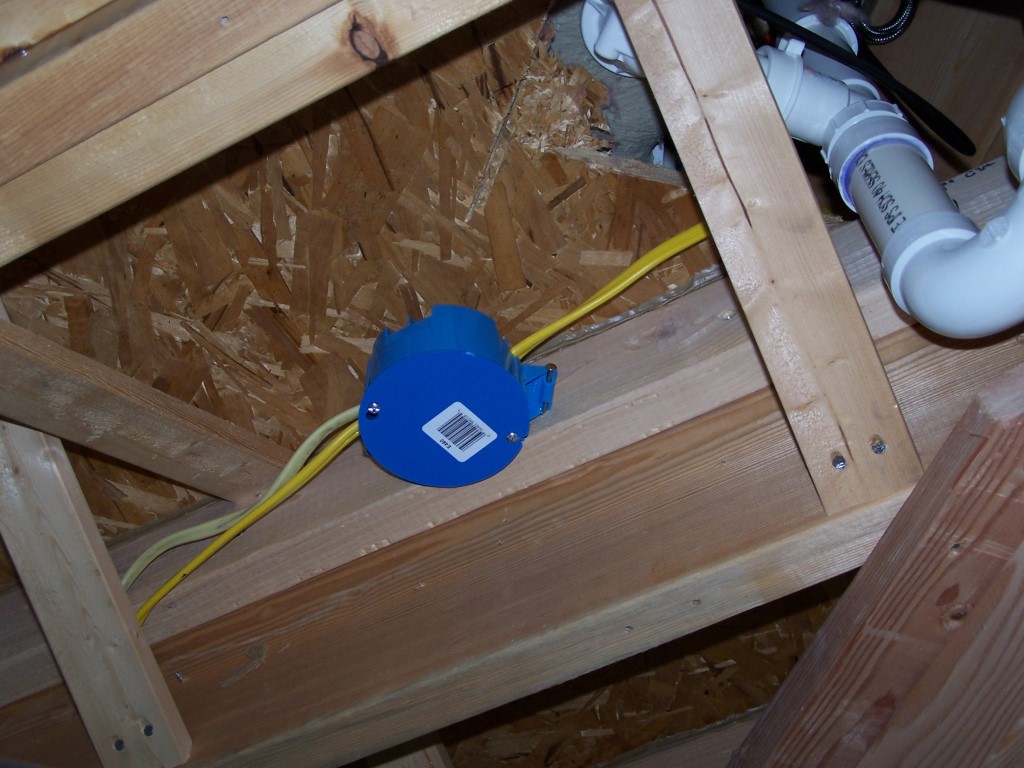
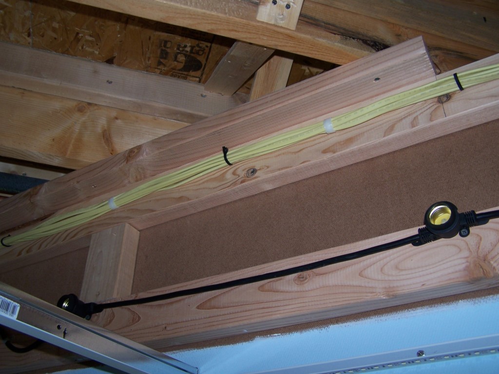
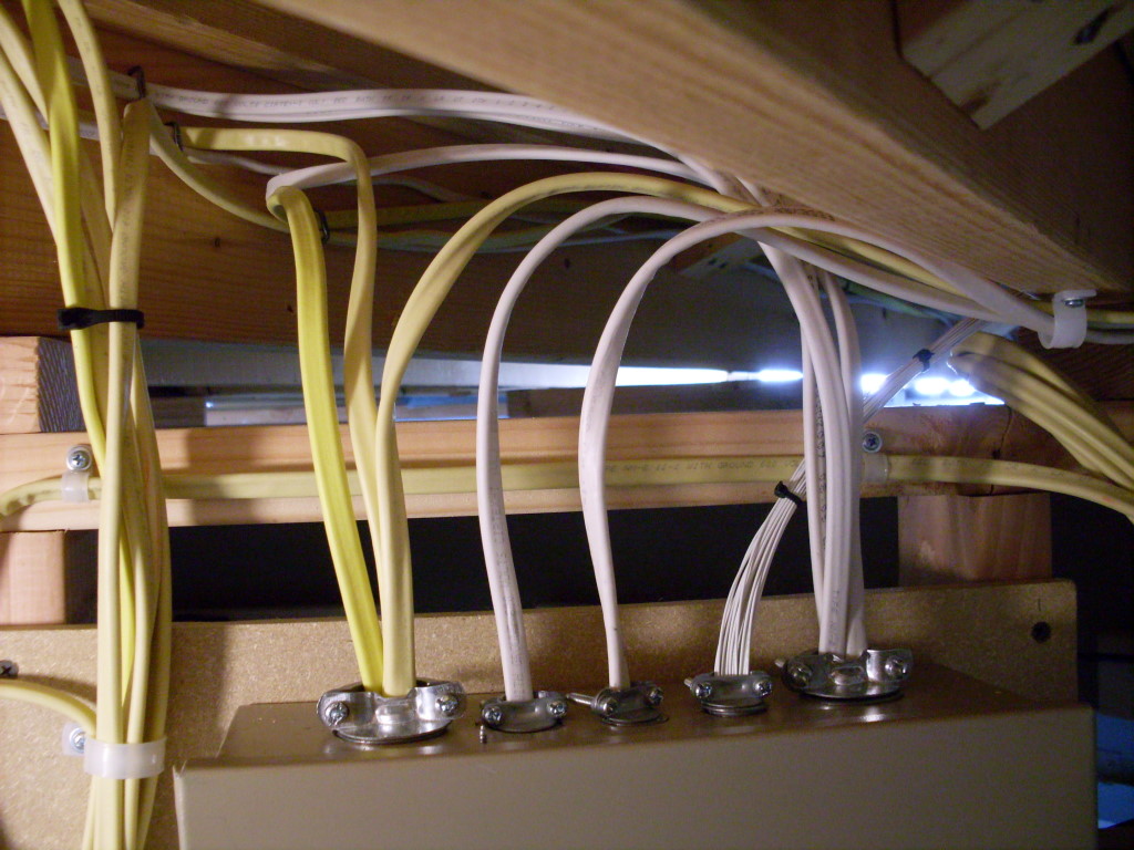
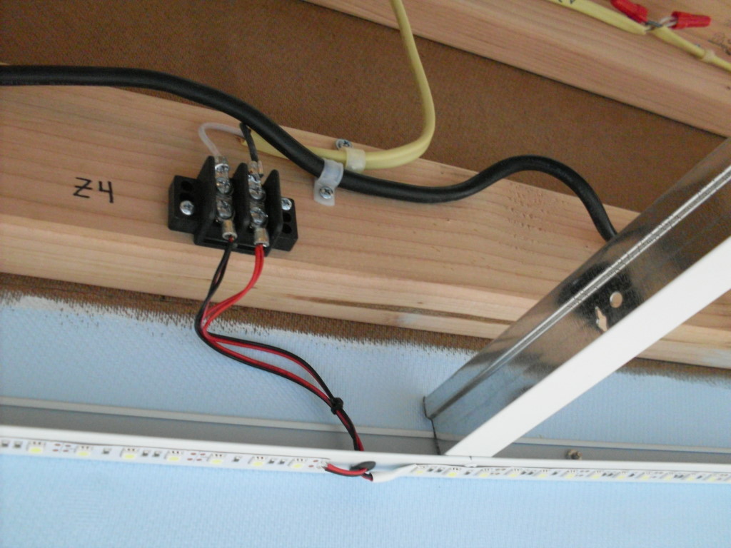
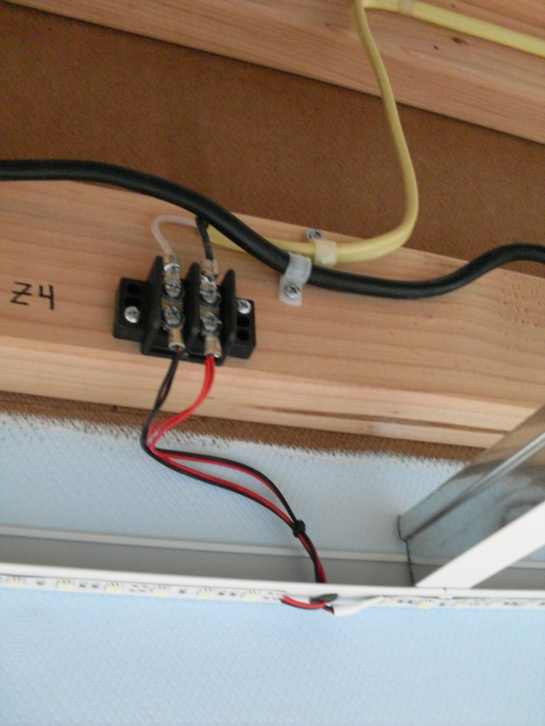
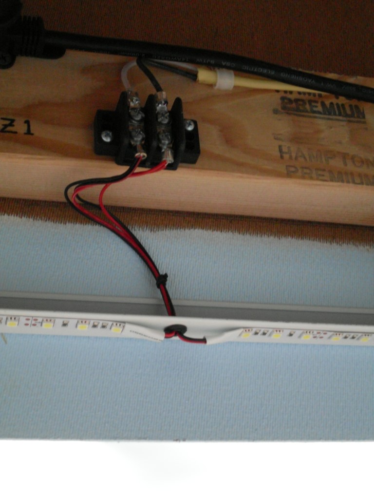
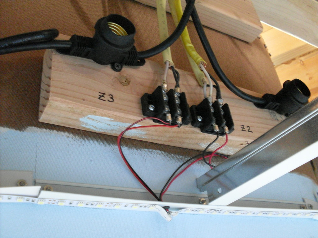
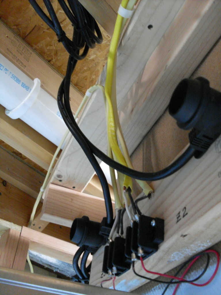
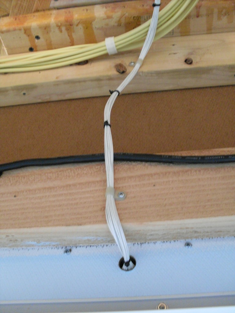
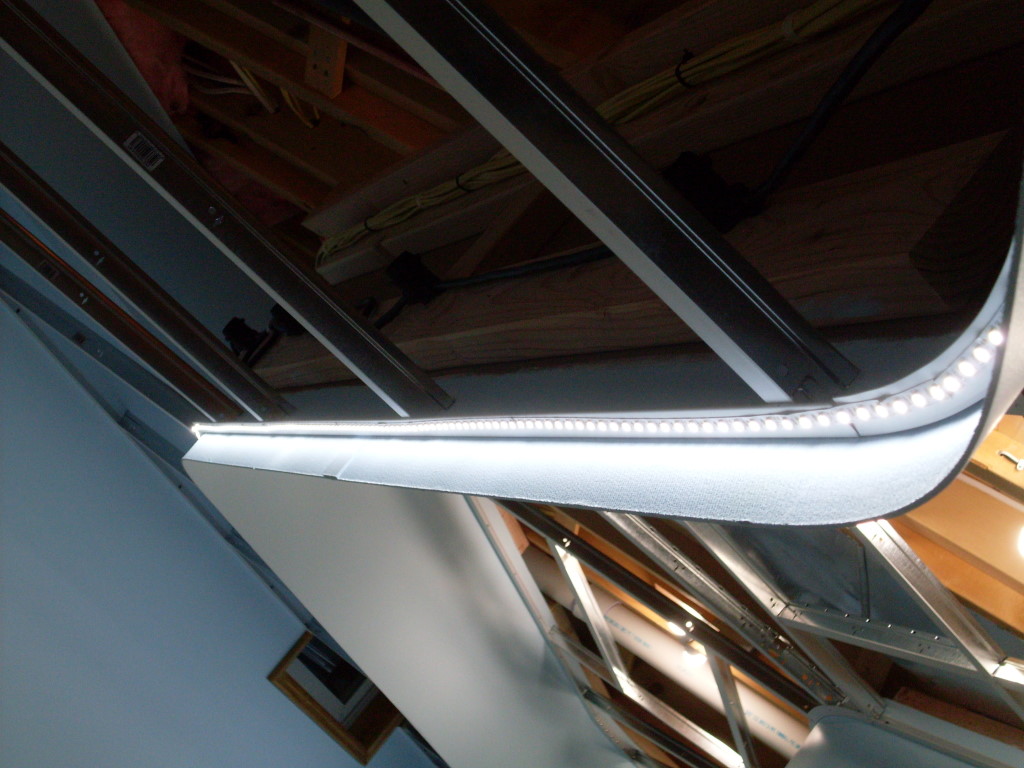
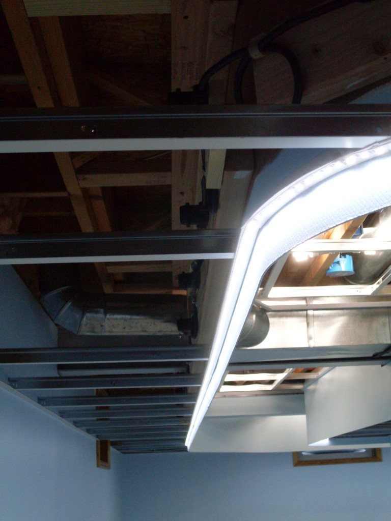
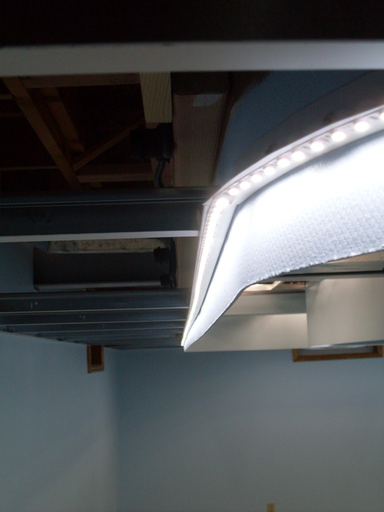
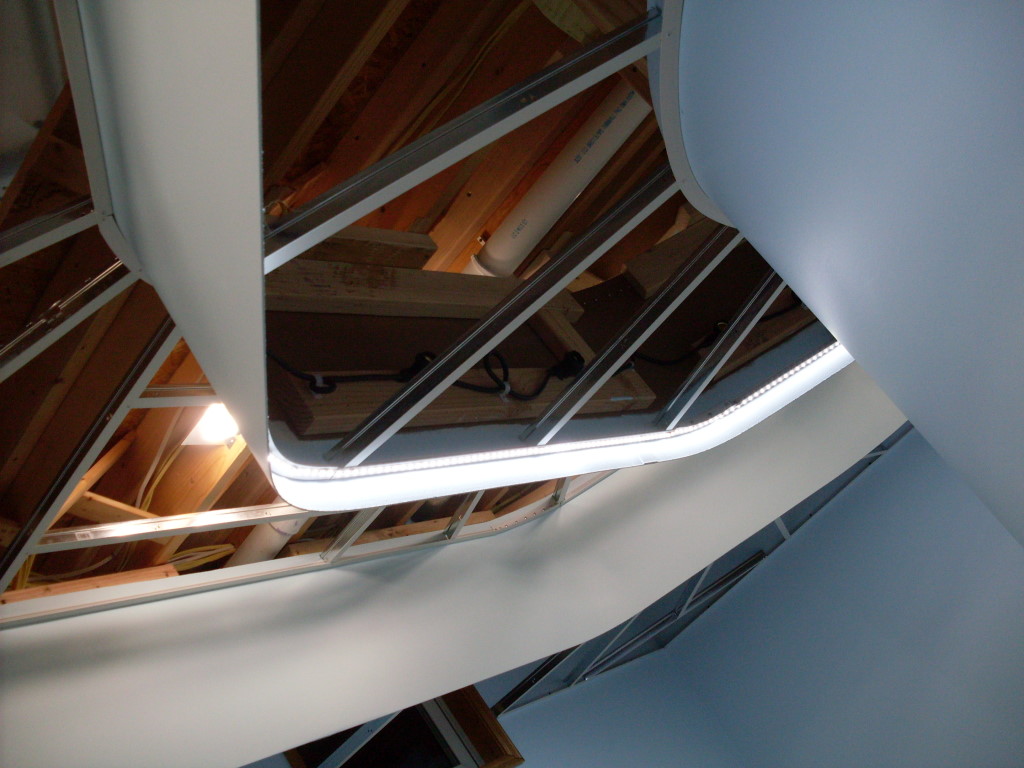
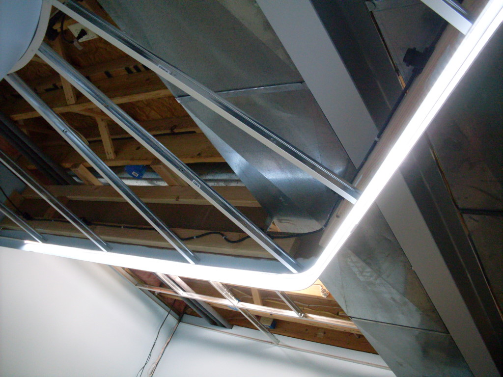
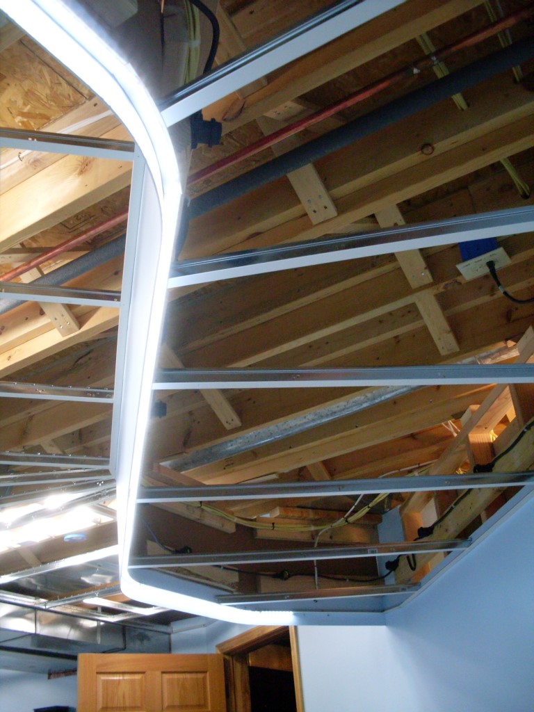
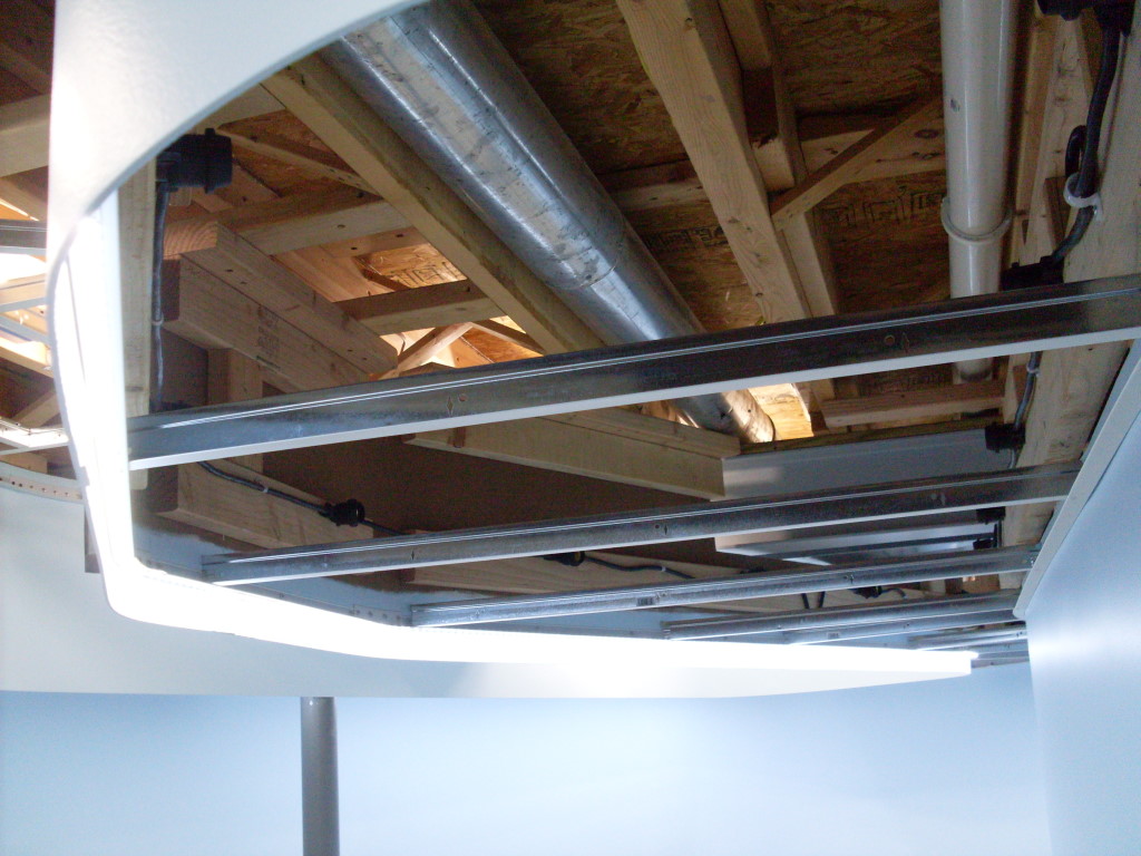
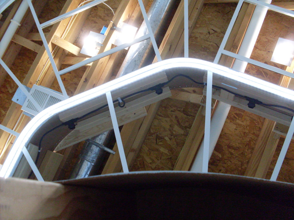
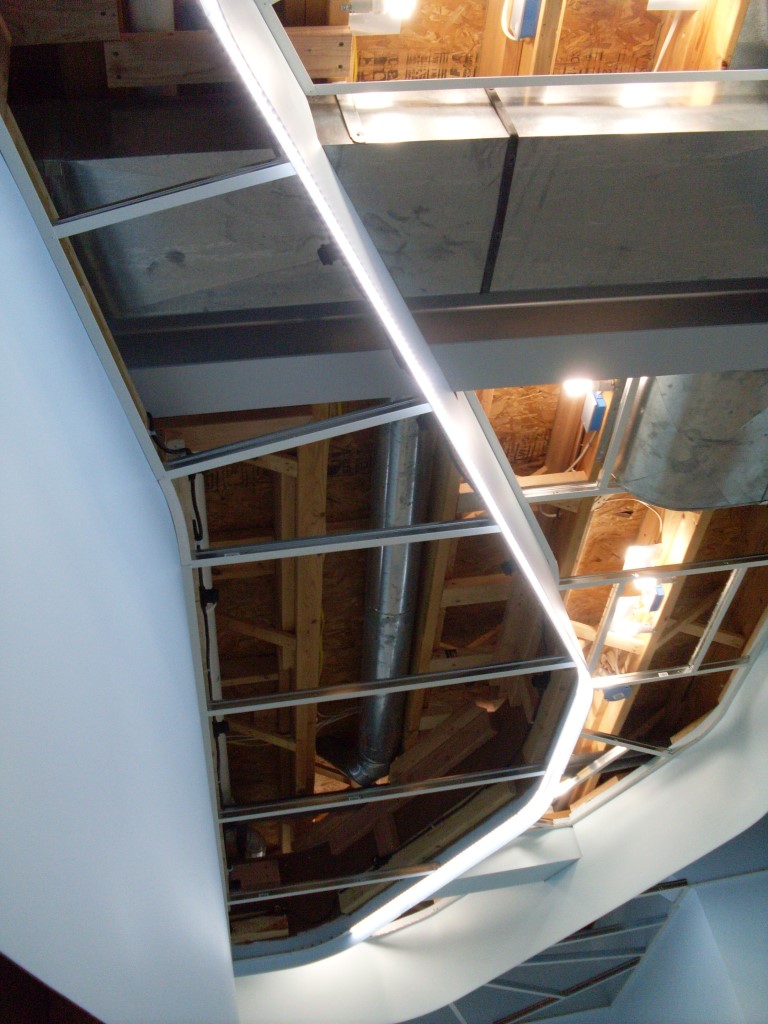
 The 12 ga Romex supplying the LED strips is routed up to the ceiling, through the floor joists, and finally terminates at barrier strips on the rear of the valance just above the connection end of the strips. The strip leads go through a rubber grommet in the ceiling panel wall angle to the barrier strip. All ring connecters are crimped and soldered. This same arrangement is repeated all way round the layout.
The Power Supplies
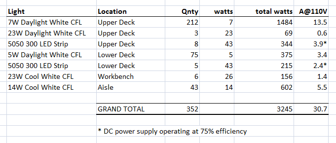
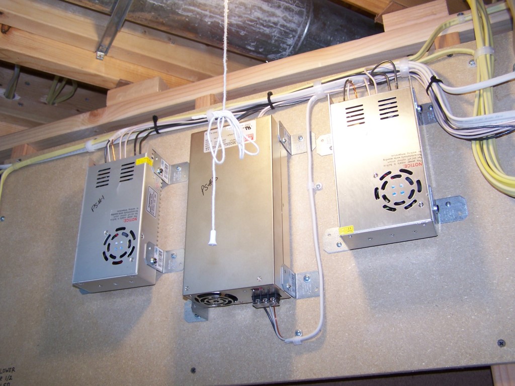
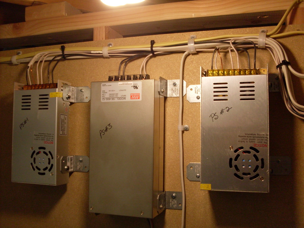
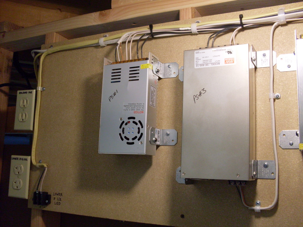
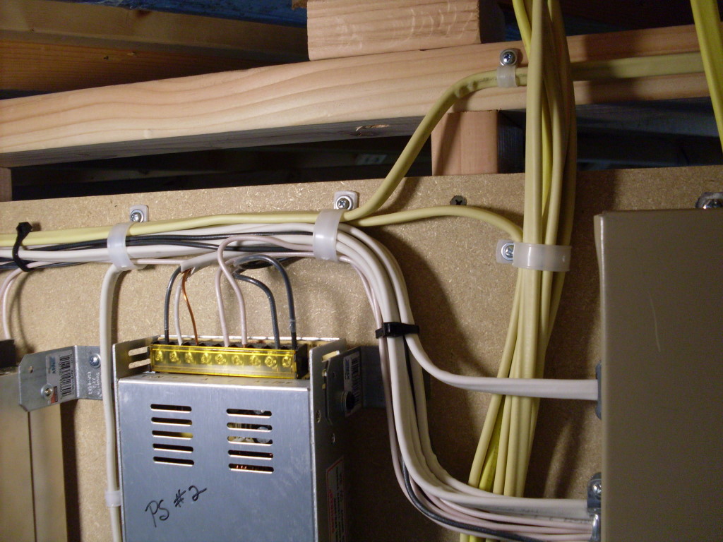
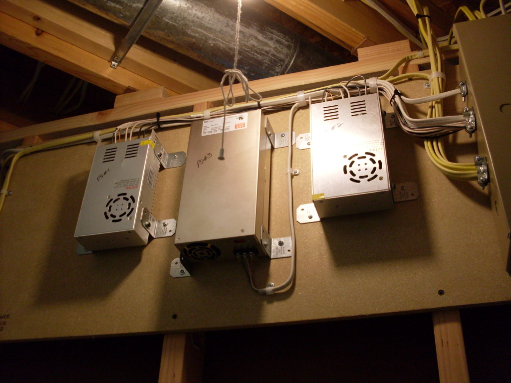
To power all of the LED strips around the layout (there are over 3,800 individual LEDs) requires quite a bit of 12v power. Additionally, I built in reserve capacity in the event I decide to add additional low voltage lighting in the future. My power supplies are switch mode so there is no huge iron transformer or gigantic capacitors. Essentially they are the same type of power supply used in desktop computers except with more oomph.  The upper deck has two 30A units (the two smaller ones) while a single 50A unit (center) powers the entire lower deck. I found that 50A is the limit before power supplies start getting real expensive. That is how I came to use two 30’s instead of a 60A unit for the upper deck. Each of the power supplies is operating at 40% of their rated current with my installed LEDs. This leaves me with enough reserve power to double the number of LEDs if desired while still maintaining less than 80% of total output from the supplies. It is not good to run the power supplies at full output for extended time. Besides, I don’t want the cooling fans to kick on. Too noisy.
The Relay Panel
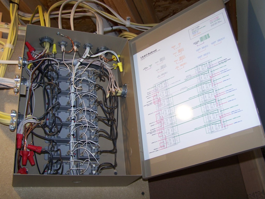
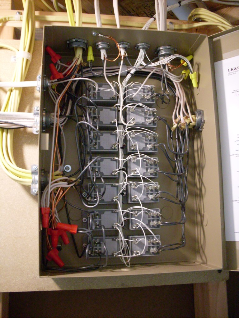
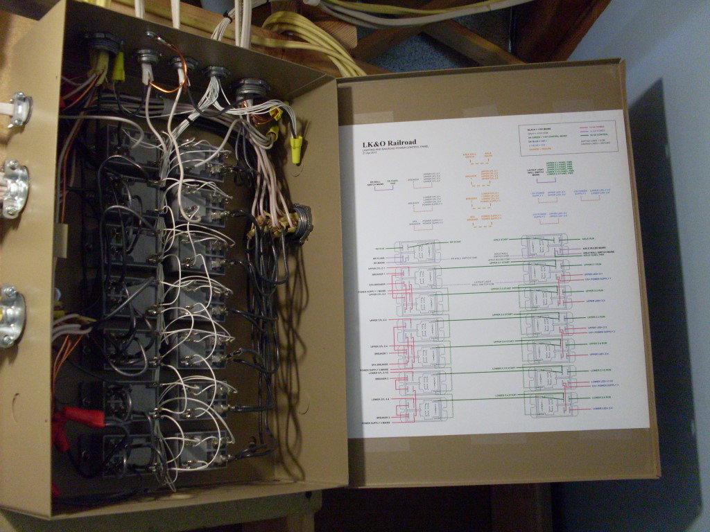
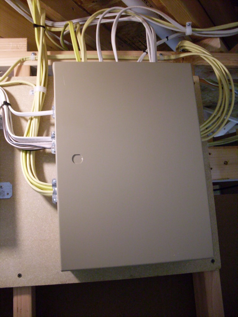
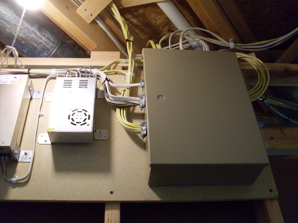
This is the heart and soul of the lighting control. The enclosure is a common unit sold for installing alarm systems. It was just the right size, has a hinged door, plenty of knock-outs, and no where near expensive as a NEMA certified box. Mounted inside are 14 Magnecraft flange mount 30A DPST power relays. These babies close with a resounding clack!
Entering the top are the supply circuits and control wires. Exiting on the right are the 12v lines to the LED strips. Exiting top left is the railroad electronics power. Exiting center left are the power supply circuits. Finally, exiting bottom left are the lines to each CFL string over the layout. Each push-on terminal is crimped and soldered. Needless to say, I spent considerable time wiring the panel. This picture of the wire scraps on the floor gives you an idea of how much cutting, stripping, and soldering went on over a period of a week.

The Zones
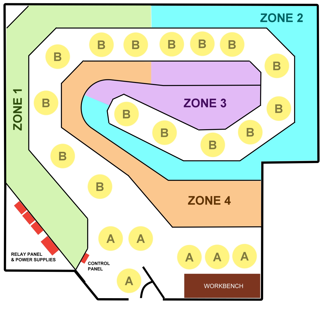
Why go to all this trouble just to turn on and off lights? Several reasons actually. Firstly, I don’t want to consume any more electricity than needed. The train room, if all on, will consume nearly 5,000 watts of electricity. Run that for a few days and see what happens to the electric bill. Being able to selectively switch on only the area that I am working in will save a lot of dollars. Next, is the problem of inrush current. There are over 150 CFL bulbs in the ceiling and lighting the layout. If turned on all at the same time the initial current demand would trip the circuit breaker. Adding to this is the high inrush current of the LED power supplies. The 50A power supply alone has an inrush current of 40A. The CFLs and the power supplies all together have a total inrush current of well over 100 amps. Ain’t no way the breakers will allow this to happen. Sequential turn on is the solution.
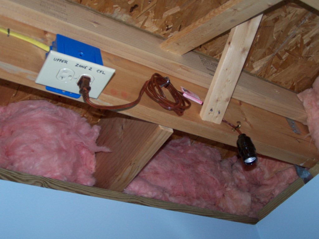
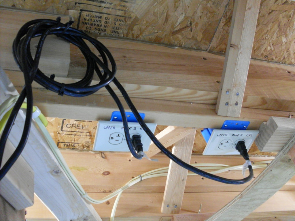
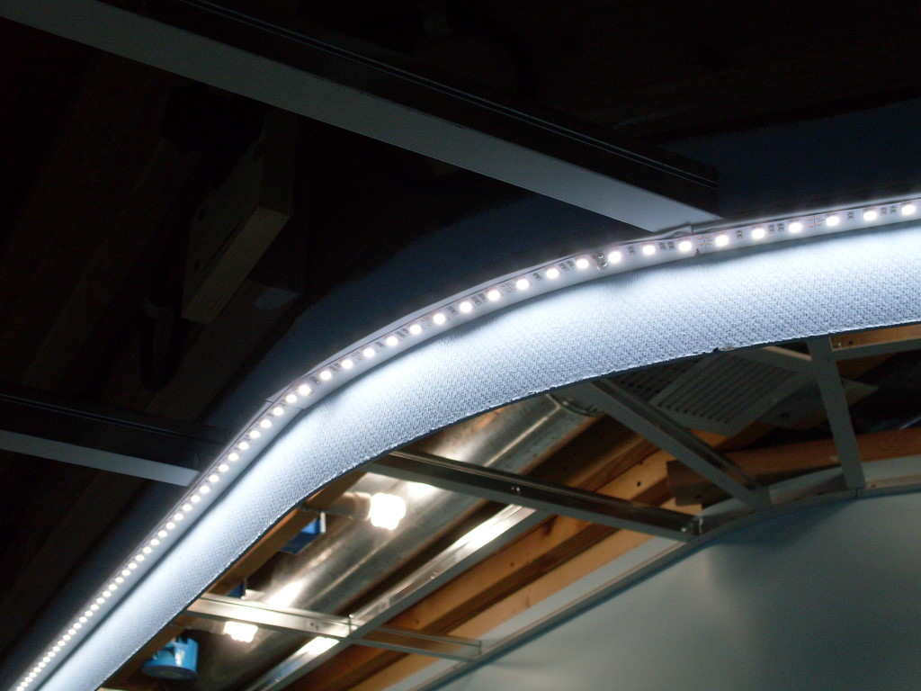
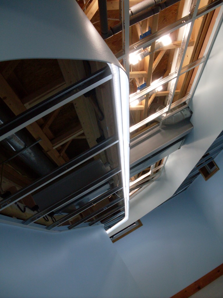
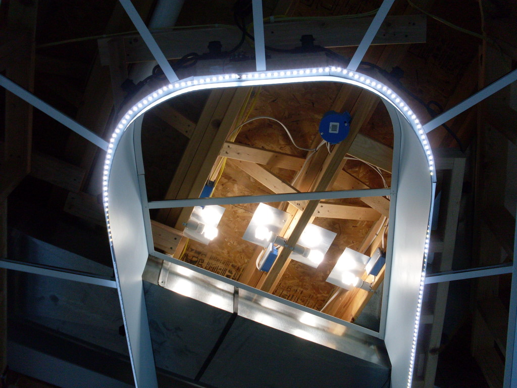
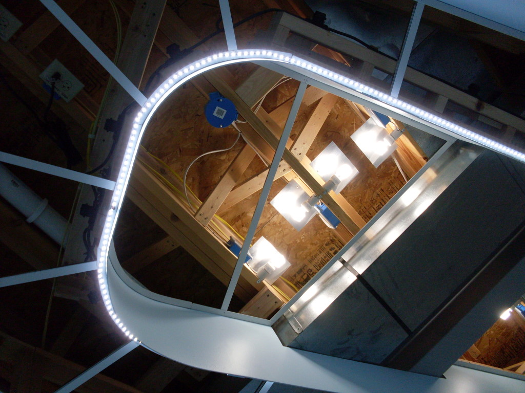
The layout is divided into 4 zones each approximately 25′ long. The beginning and end of each zone is determined by the party light strings mounted earlier. The LED strips were fashioned to mimic the party light start and end points.  The lower deck has no zone 3 due to the arrangement of the track plan. For any given zone, the LED strips and the CFLs are controlled in unison. There are additional CFL fill light sockets mounted in the corners of the room, marked (C), where the layout follows the corner. This is needed because the layout CFLs are mounted to the valance which, in the corners, is quite far away from the center of the corner. 23 watt (100 watt incandescent equivalent) lamps will be in these sockets. There are no bulbs in any of the sockets in the pictures. I have yet to buy them!
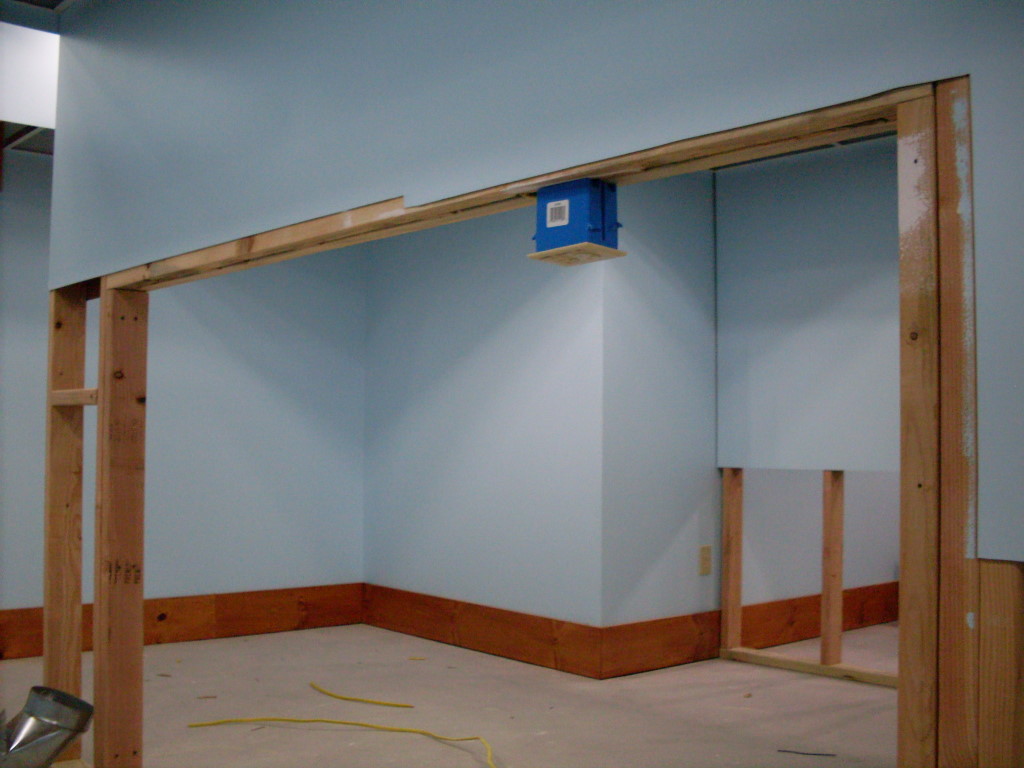
The aisle lamps are also controlled by push buttons. When you enter the room and flip on the light switch only the ceiling lamps marked (A) will light. This provides light in the entryway and over my hobby workbench. Pressing the aisle button lights the lamps marked (B). Another electricity saving design feature.
So there you have it, my lighting solution for the LK&O Railroad. Be sure to check out the photo gallery below. Tons of pics. I am going to let my side cutters and soldering gun rest for a while as I move on to building reflectors for the layout CFLs. Thanks for reading!


Wow! It looks really nice Alan.
Thanks Greg. Can’t wait to see the whole finished system light up. Am still buying out the local Home Depot of 9W daylight CFLs. 20 more bulbs to go!
Alan,
Nice blog, nice work on the lighting too.
One comment on your schematic of the light control. The top switch labeled “OFF” should have the iverted “T” below the contacts in order to function properly.
Regards,
Bernd
Thanks for the compliments Bernd. Good spotting on the schematic. As drawn it would be a “pull” button switch! 🙂
The actual wiring deviates from the schematic anyway so I need to post a correction to more than just the switch. Next post.
Alan,
Do you really have 1950 feet of the TYCO wire left over? Would you like to sell some or all of it? I have all the parts to build a similar lighting relay control panel and I’m shopping for the pushbutton hookup wire. I’m not finding anything on eBay similar to what you found.
BTW: I’ve read all your LK&O blog posts and I eagerly await each new entry. You’re at the top of my Blogs I follow list. I’m ‘AM David” on the MRH forum.
Regards,
David
Dave, yes I do have the wire however it is earmarked for the Tortoise-to-fascia-panel wiring. This will require hundreds of feet of wire by the time it is finished. I don’t want to sound stingy but it would be a bummer to get 90% of the way done only to run out of wire. If you are in no rush I will gladly help you out once my fascia panels are finished.
Try searching ’24AWG UL1007′ which is 300V wire.
http://www.ebay.com/itm/UL1007-24-AWG-HOOKUP-WIRE-BLUE-REEL-OF-1000-/350697740250?pt=LH_DefaultDomain_0&hash=item51a736d7da
Alan, Totally understand that! Thanks for the link.
[…] green. All returns are white. All non-specific polarity wiring is also white only because I have a monster roll of white wire left over from my layout lighting installation. Keeping track of where each white wire goes is accomplished with labels. I have always found label […]