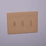
Three wall switches were installed next to the doorway when the train room was originally constructed. The intent was to use one for conventional room lighting, one for layout lighting, and the third for all of the railroad electronics. The idea being I could turn off all three switches when leaving the room and be assured everything is powered down. Well, the best laid plans of mice and men…..
The wall switches are all fed from a single 15A circuit. Looking back I wish I had given consideration to just how much juice the room will need. Turns out it is way more than 15A. Take a look at the power requirements just for lighting:
| Lighting | Type | Output Wattage | Input Amperage |
| Upper Deck String 1 | CFL | 24 x 9W | 3.6 @ 115V |
| Upper Deck String 2 | CFL | 24 x 9W | 3.6 @ 115V |
| Upper Deck String 3 | CFL | 24 x 9W | 3.6 @ 115V |
| Upper Deck String 4 | CFL | 24 x 9W | 3.6 @ 115V |
| Upper Deck 12v Supply 1 | LED | 360W | 5.0 @ 115V |
| Upper Deck 12v Supply 2 | LED | 360W | 5.0 @ 115V |
| Lower Deck 12v Supply 1 | LED | 360W | 5.0 @ 115V |
| Lower Deck 12v Supply 2 | LED | 360W | 5.0 @ 115V |
| Room | CFL | 50 x 9W | 7.5 @ 115V |
The total amperage for the entire arrangement is 41.9 amps. That is a whopping 4,818 watts of electricity! Fortunately, rarely will it all be on at once. Only during a full fledged operating session will all of the layout lights be on and then the room lighting won’t be needed. When I am working on the railroad I will need to turn on just the room lights and the layout lighting in the area where I am working. Thank goodness. I would need a second job to pay the electric bill if all the lights were all on a lot.
As you can see there is no way to power all of the lighting from my single 15A circuit presently installed. I have a solution however. First, there is one last open breaker spot left in the load center. I will pull a fresh 20A circuit from that spot. Second, there is an existing 20A circuit dedicated to the jet tub in the master bath. The bathroom is directly above the train room so the wiring crosses through the floor joists above the layout. A jet tub is cool and all but we rarely use it. I am going to put a junction box in the tub circuit so I can tap in. The layout lights can’t be on when the jet tub is running but no big deal. The jet tub has been used less than 10 times in all the time we have lived here so coordinating between use of the tub and lighting the layout should be no problem whatsoever. This combination provides me with two clean 20A circuits and the existing 15A circuit. All total that is 55A which when de-rated 20% for continuous duty equals 44A. Sweet!
Even if I can’t turn on all the layout lighting from the wall switch I still want to be able to at least turn off all the layout lights with the wall switch. For that I have come up with a solution.
 * Everything inside the dotted rectangle is replicated for each of the load circuits in the table above except for room lighting
This circuit uses momentary contact push buttons and DPST relays to turn on/off each individual leg of the lighting circuits. The relay coils are powered by the existing wall switch circuit (which also powers room lighting) while the relay load contacts are powered by the 20A circuits. Turning on wall switch #2 will “arm” the push buttons. Depressing the ON push button will energize the coil. One set of contacts is wired so as to keep the relay coil energized after the push button is released. In effect it is a do-it-yourself latching relay. Turning off the wall switch will cause the relay to de-energize and the contacts will open. Now I can flip the wall switch on the way out and all layout lighting will go out. There is an OFF push button so I can, if desired, turn off sections of lighting without turning everything off and back on again.
Digikey has the relays I need in stock and a huge selection of decorative push button switches of sufficient rating. I plan to make a nice looking back-lit acrylic switch panel with labeling and put it on the lighting valance near the train room door. Walk in, flip the wall switch, push the buttons only for the layout lighting needed. When done, flip the wall switch and walk out. Cool, huh?
The room lighting will be conventionally controlled by wall switch #1. Train electronics will be powered by the wall outlet circuit which is totally independent of the lighting circuits. There, a single simple relay will be powered by wall switch #3.
Problem solved and it will all work as intended!

Leave a Reply