Installation of the first completed module onto the layout went really well. There was only a single oopsy along the way. More on that in a moment.
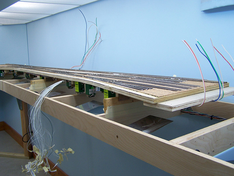
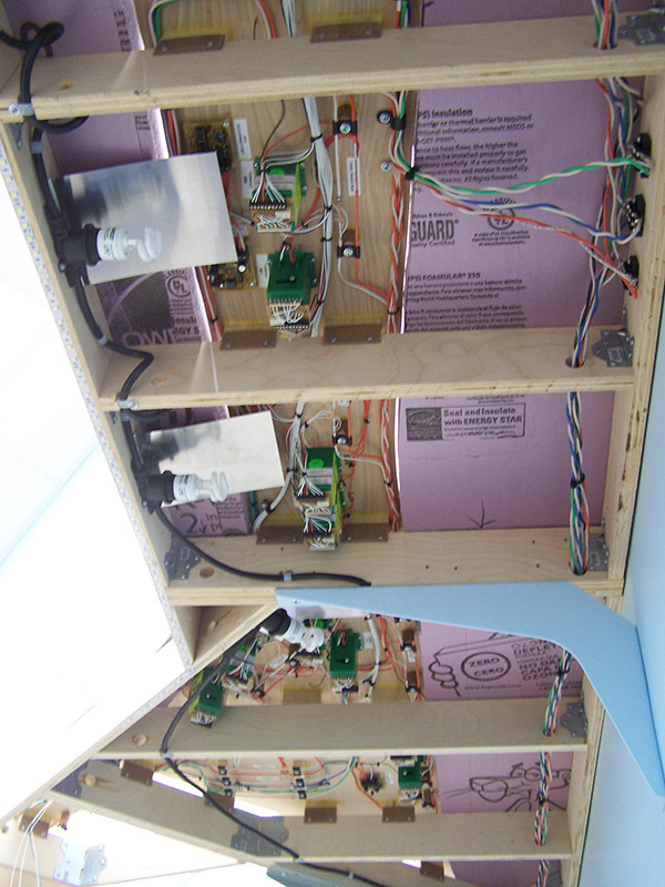
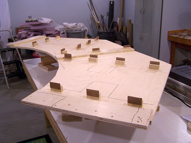
Three boards were positioned on crossmembers to allow the module to be placed in position except 3″ higher. I did this because I wanted to check clearances of the module components to the lighting reflectors. I knew from the get-go that an occasional reflector may need trimmed. The boards were secured with masking tape on both sides so they didn’t fall off if bumped while hoisting the module in place. The module is long and now quite heavy. It is a little awkward to lift into position.
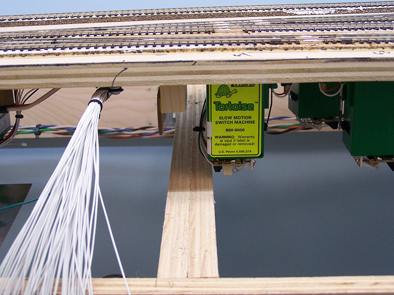
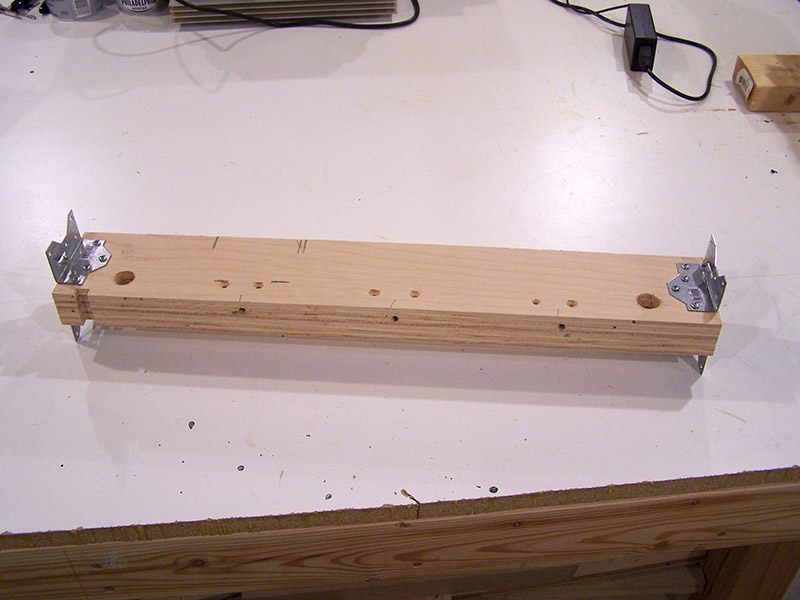
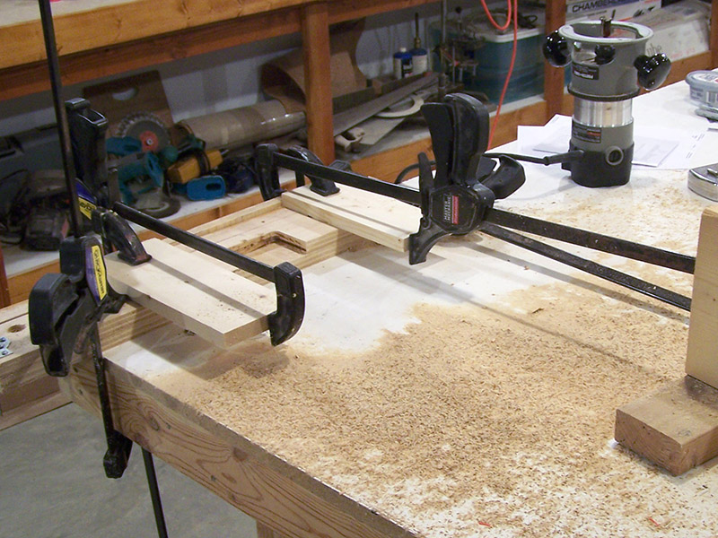
Good thing I put the module up on spacer boards. It kept a mistake of mine from destroying a Tortoise switch machine. Seems my Tortoise positioning drawing did not include the doubled thickness of crossmembers that are on mounting brackets. I went back to the benchwork drawing and it shows double thickness crossmembers but for some reason they never made it to the latter drawing. The drawing is fixed now. As for the Tortoise/crossmember interference problem, that is fixed now too. Mistakes are bad but in this case an opportunity to demonstrate an advantage of benchwork construction with nailing plates and screws. In under five minutes the crossmember was out of the benchwork. Remove a few screws with the screw gun, disconnect a few wires at their terminal block, and presto! Crossmember on the workbench for router work. I clamped together a router jig and went about hogging out a recess with a 3/4″ straight cut bit. The crossmember went back into place as easily as it came out. Problem solved.
As I mentioned, two reflectors did need trimming. A snip on the corner of one and a length shortening of on another. No big deal. Very pleased that so little reflector modification was needed.
With alterations made I set the module down into its final position and reinstalled all of the riser screws.

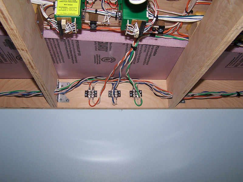
It is better to be lucky than good they say. Certainly applies here. It seems I placed a point rails wiring peg in a no-go zone above a crossmember. Same problem as before – lack of double thickness crossmember indication in the drawing. Fortunately, luck covered my butt. The peg is just short enough that it causes no interference problem. Even with the drawing corrected the lesson learned is to do a better job of marking the underside of the sub-roadbed before I pull it off the benchwork. That way I will have the drawing and marks to keep similar mistakes from occurring in the next modules.

The last remaining task was to connect the module to the power buses. Cut, solder, attach. Exactly how it was meant to work.
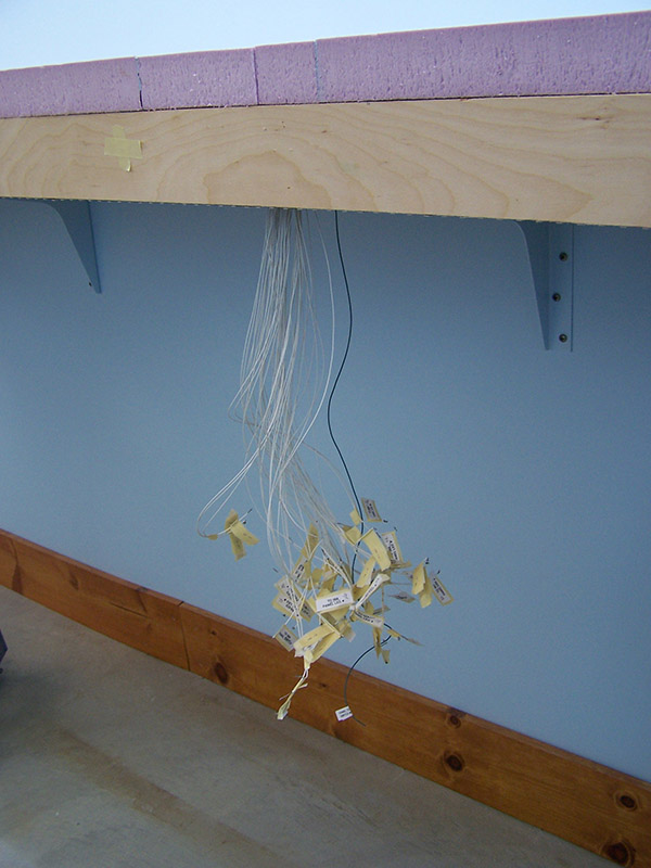
I couldn’t help myself but to power up the railroad and run a train. It ran well. Playing didn’t last long because I can’t operate turnouts just yet. Fascia control panels need to be built. But that has to wait until track is laid on all modules. For now a bundle of wires hang out of the bottom waiting.
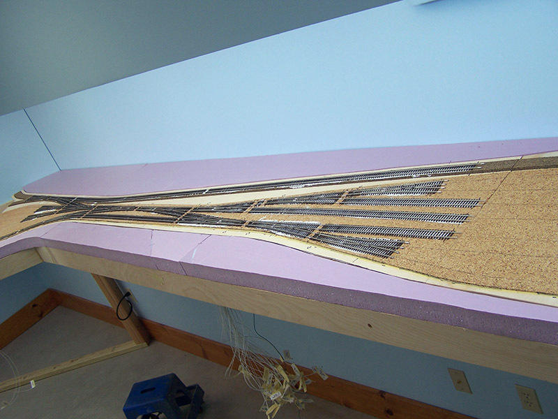
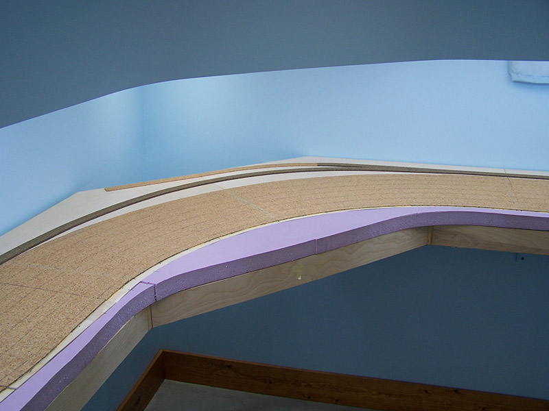
The module in place with foam reinstalled. Module #1 is done.
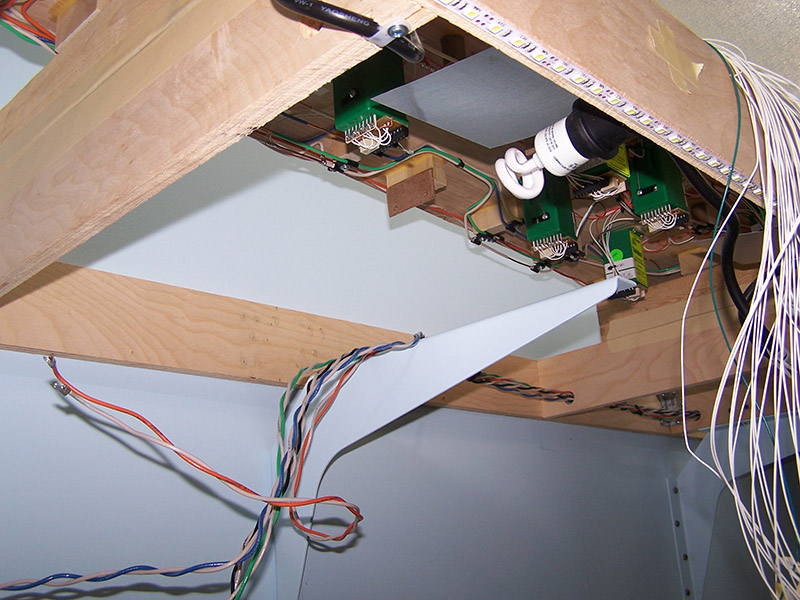
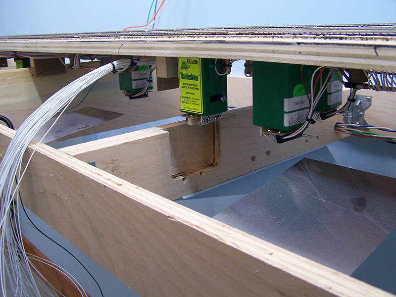
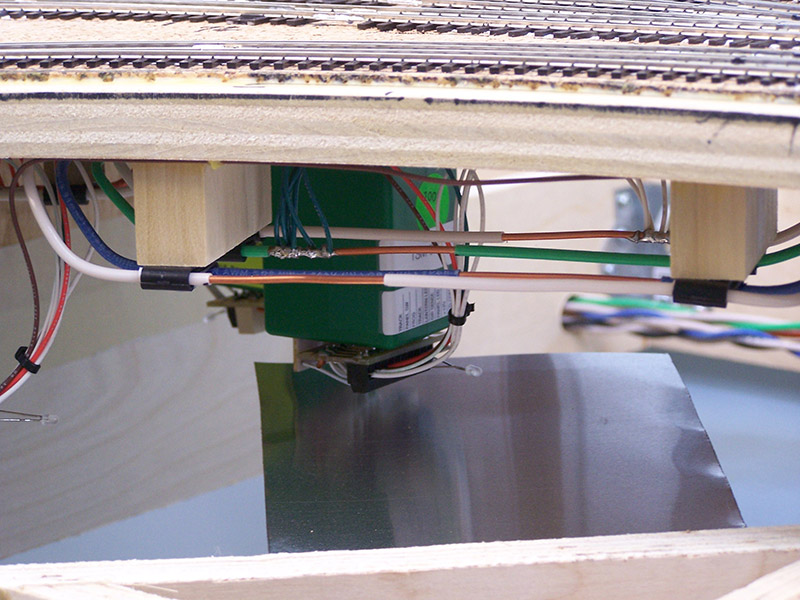
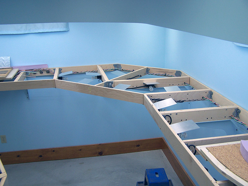
Here is a view of the underside. Even though the module is dense with wiring, the remainder of the underside is pretty much open. That space will fill up over time as additional electronic gizmos are added along with wiring for structure lights, signals, animation, etc.
Building module #1 was an adventure. I learned a lot along the way. From here on it will basically be lather, rinse, repeat. Let the lathering begin! Module #2 is on the workbench.

Leave a Reply