With the power buses and track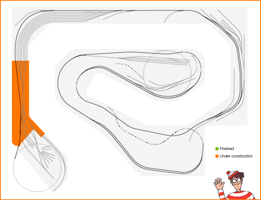 feeders in place it was time to move on to the control and accessory wiring – running and connecting each wire to its appropriate place beginning with Tortoise to fascia panel wiring and finishing with accessory and control power wiring.
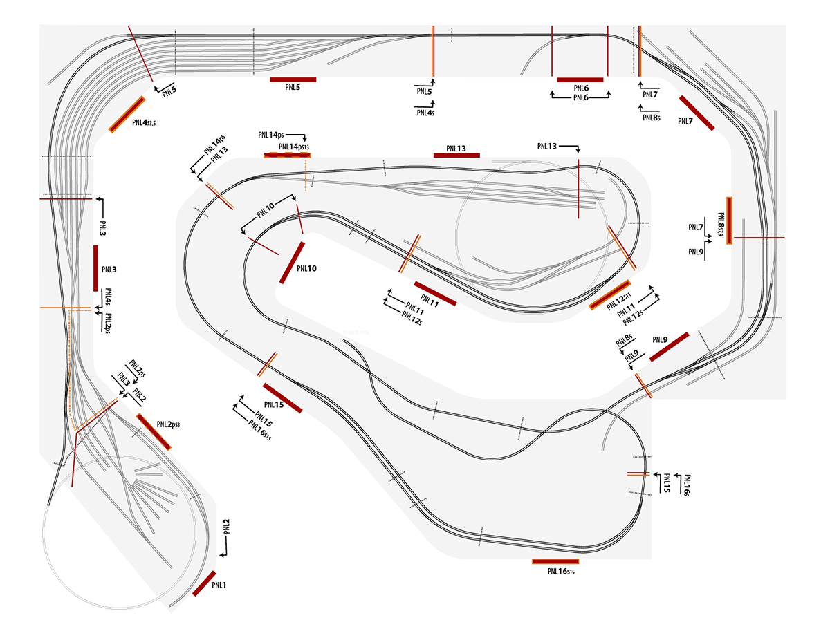
The position of the fascia panels on the layout were determined before the first module was removed. They are marked with masking tape Xs on the benchwork and a label on the module so I know where the panel wiring exit point is located. The same was done for the power connections to the benchwork mounted power bus. 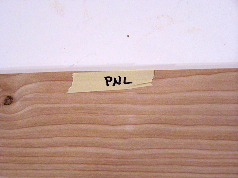 Below is a diagram of the panel positions. The arrangement was determined by where an operator will likely stand while working a particular section of track, specifically actuating turnouts. The panels shown with a dotted orange outline are slave panels to adjacent panels. The part numbering syntax indicates this with a lower case “s” appended, or lower case “ps” for partial slave. The number(s) following the “s” or “ps” indicate the primary panel the slave panel
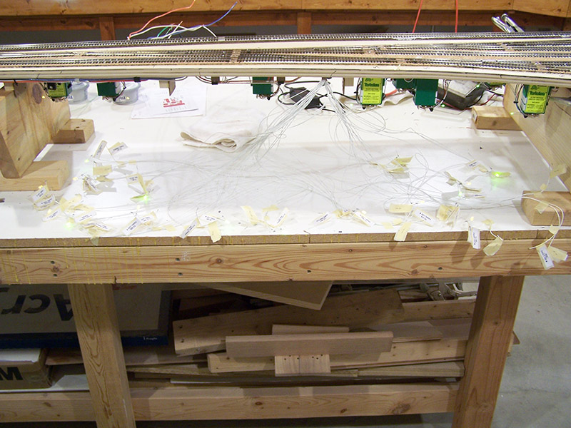
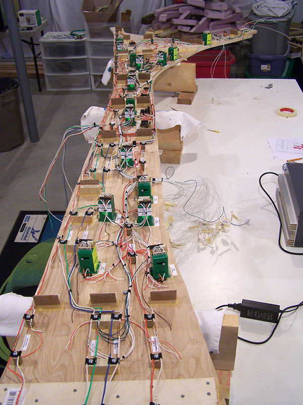
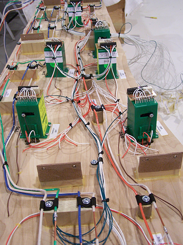
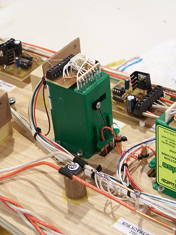
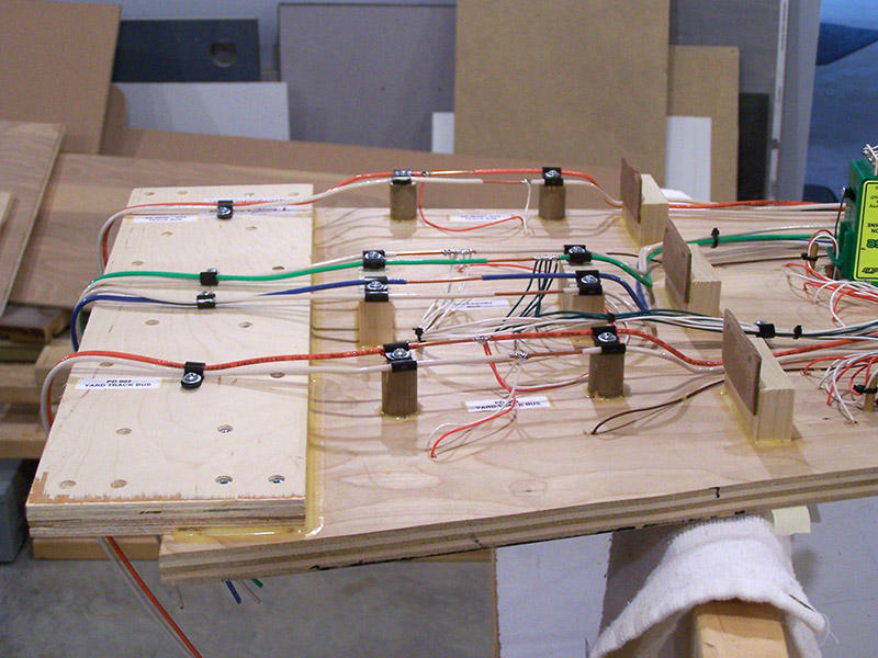
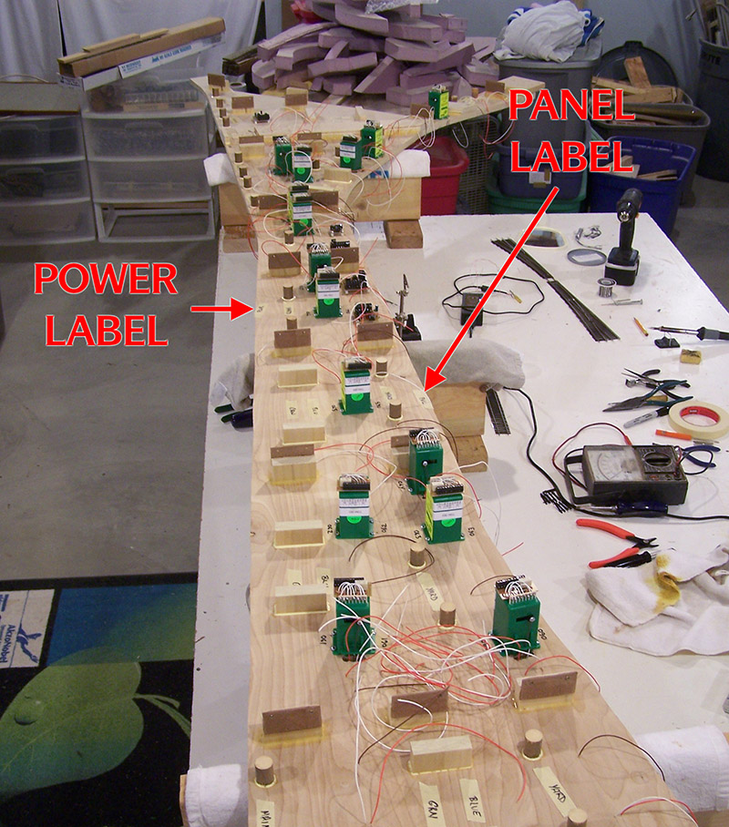 is tied to. Operation of turnouts can now be performed from more than a single panel. Hopefully this will reduce the amount of operator passing in the aisle when more than one person is working the same area. More on this subject in a later post when I install the fascia panels. I mention it here for one reason. Only primary and partial slave fascia panels are wired to any given module. Full slave panels will be wired to their respective primary panel(s). Hence why you don’t see a corresponding bundle of wires for each fascia panel exiting a module. Only primary and partial slave fascia panels have a bundle of wires exiting the module. This is best illustrated on module #1 in the following image. Tortoise 058 at the far end of the module is primarily controlled from panel PNL2ps3. It is the only Tortoise on module #1 that is not controlled from panel PNL3 therefore it has its own wiring exit point from the module.
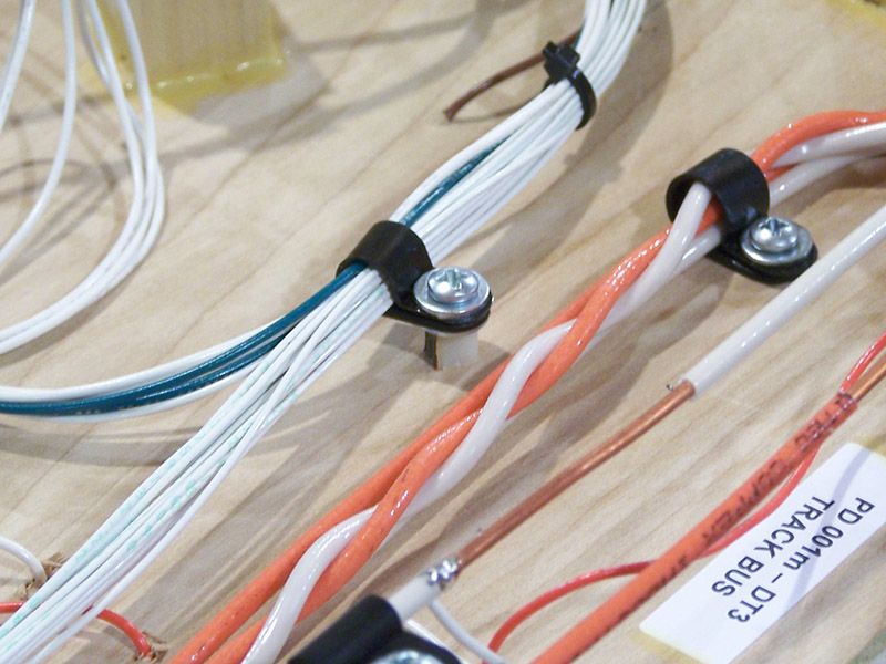
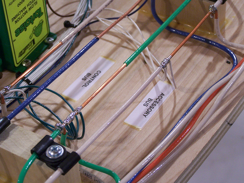
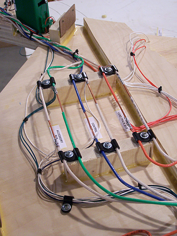
I am using 24AWG stranded wire for all interconnects on a module. Following with the color coding scheme, track power is orange, control power is blue, and accessory power is green. All returns are white. All non-specific polarity wiring is also white only because I have a monster roll of white wire left over from my layout lighting installation. Keeping track of where each white wire goes is accomplished with labels. I have always found label adhesives to be a bit of a paradox. Why do they fall off when you want them to stick yet do anything but come off when you want to remove them? One of life’s many mysteries I suppose. Taking no chances I put a staple through each of them.
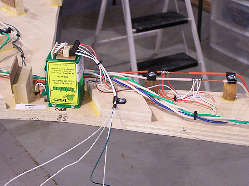
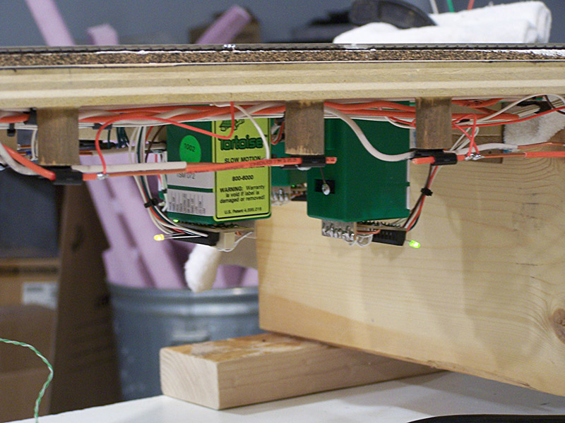
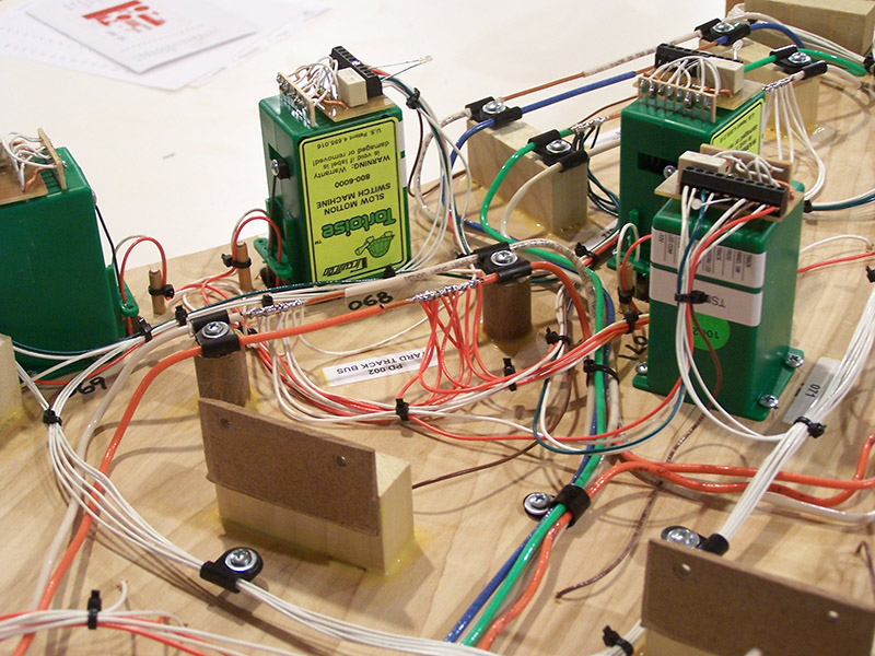
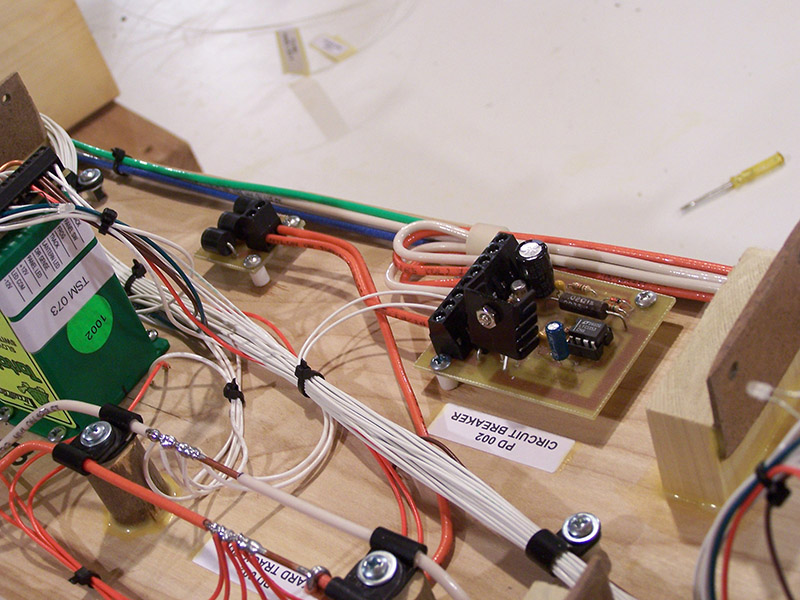
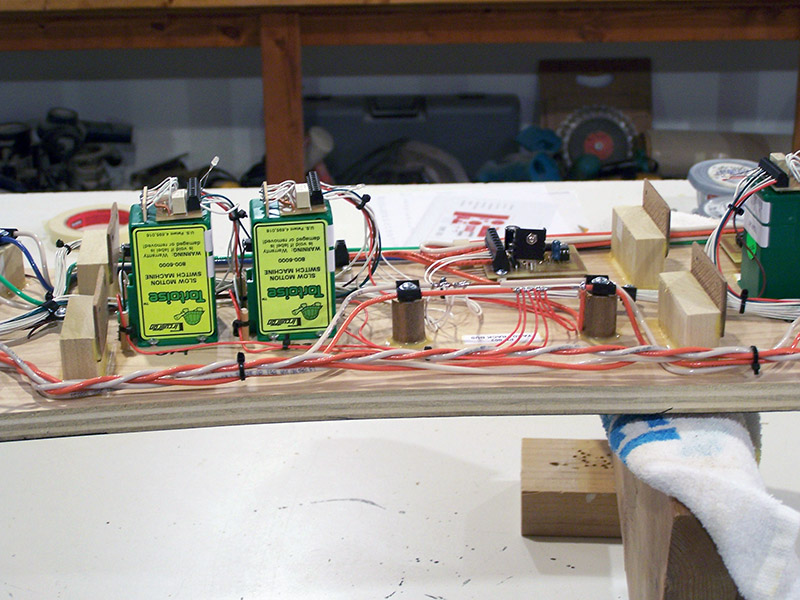
At each Tortoise connection there are several wires:
- Power to run the Tortoise coming from the accessory bus (green, white)
- Lead going to the fascia panel momentary contact switch (white)
- Two leads going to the fascia panel direction indicating LED (white)
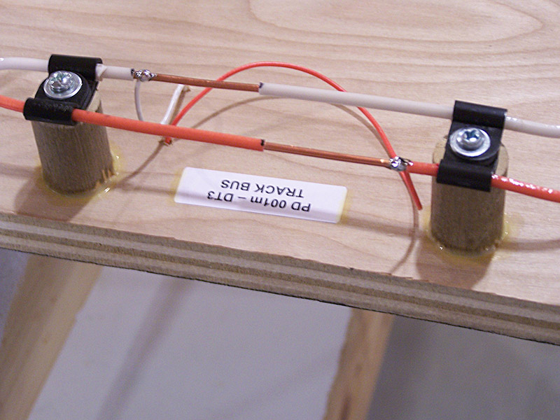
- Power for the frog coming from the track bus (orange, white)
- Frog connection (brown)
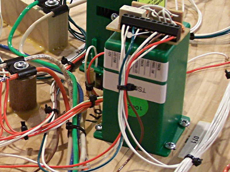
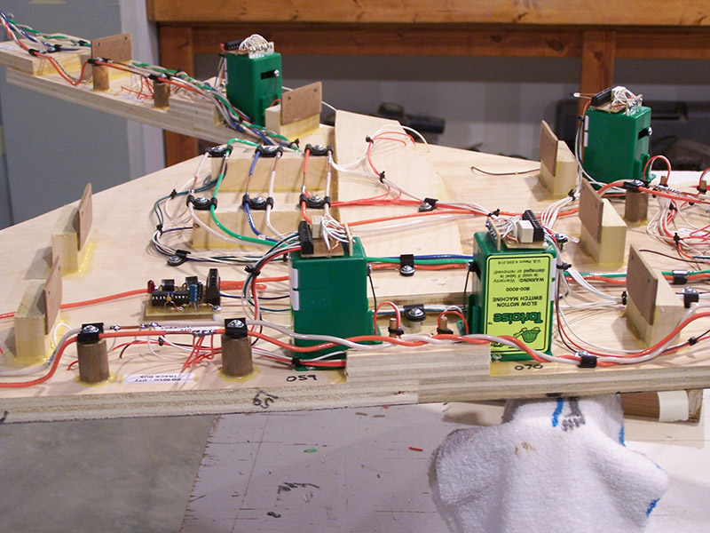
Eventually there will be another pair of wires connected to the Tortoise for the switchstand lantern. Those come later. Because the Tortoise will not operate without the switchstand lantern (wired in series) a bi-color LED is placed temporarily at the connector. I should note the green hookup wire I purchased is more of a teal color than bright green. In person it is easy to distinguish from the blue hookup wire. Due to the fact that I use a cheapo point-n-shoot camera (workshop too dangerous of an environment for the good camera) the white balance is different on every picture making the green (teal) accessory wire look blue in the above picture.
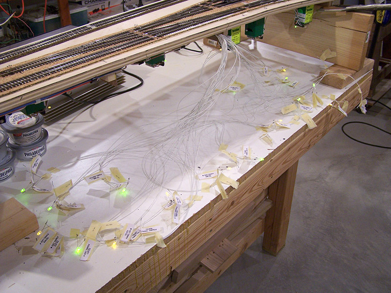
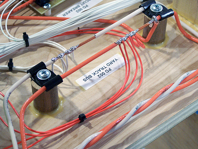
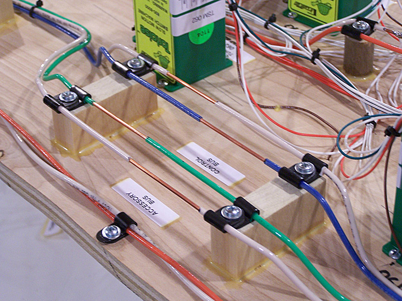
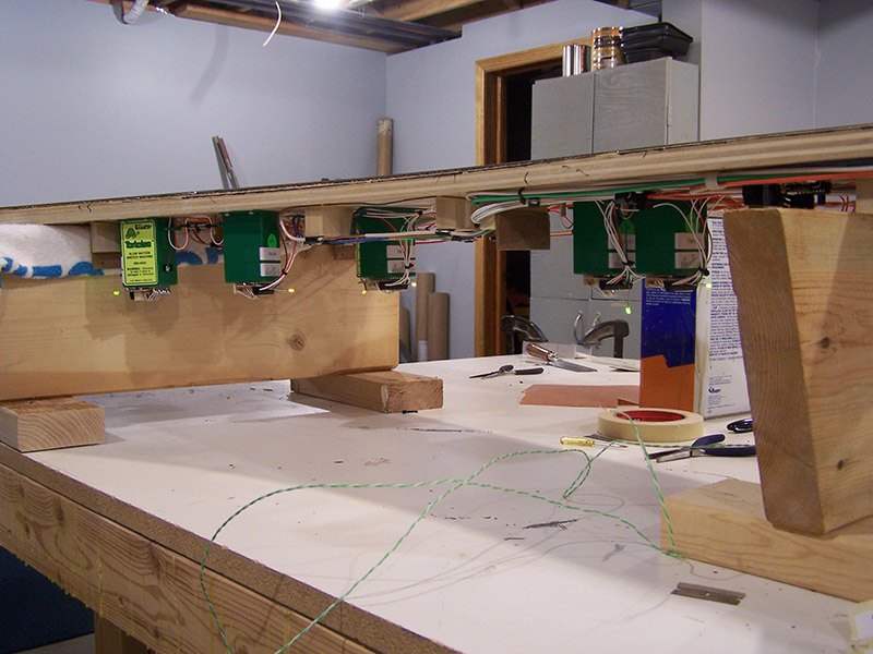
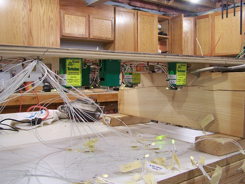
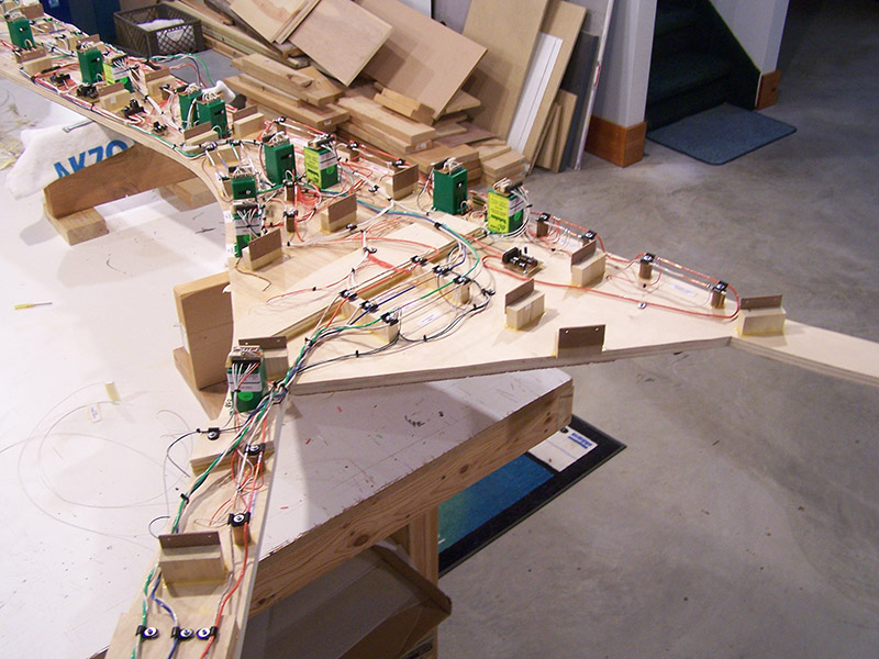
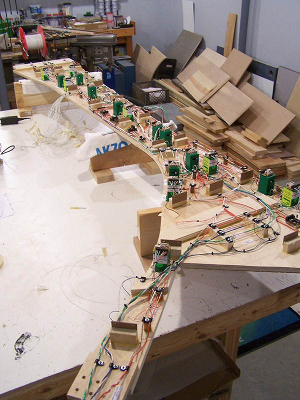
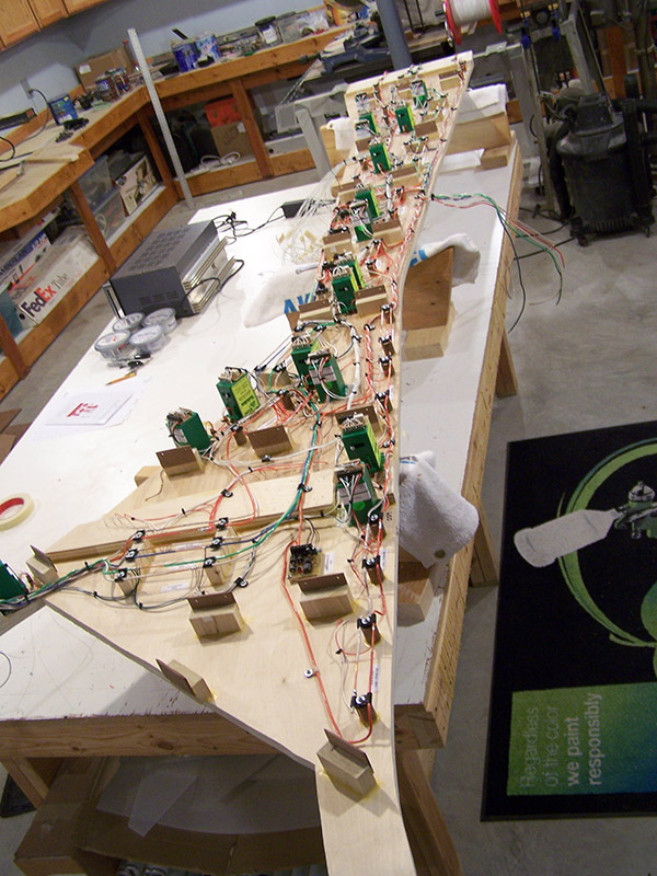
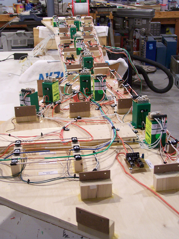
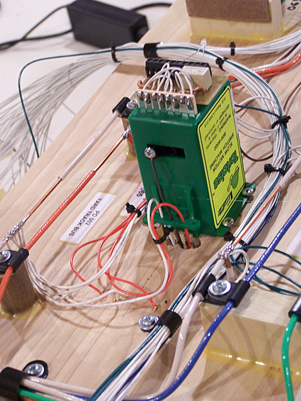
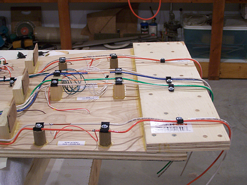
I like my wiring both electrically and mechanically secure. I also like neat and tidy although that is a relative term to be sure. To that end I routed the fascia panel wiring in one common bundle for the length of the module. Initially I used masking tape bits to keep installed wires in rough alignment. Once all wiring had been installed I went back and bundled them securely with wire ties and nylon clamps allowing the excess wire lengths to equalize at the panel connection exit point of the module.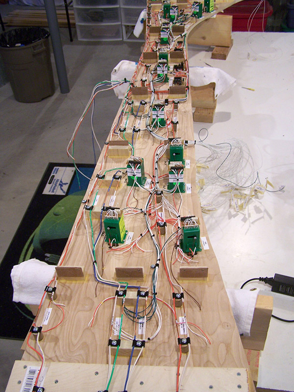 As you can see the underside of the module has become quite crowded with wire. Not a problem for the wiring itself of course but does present a potential danger. Throughout the life of the layout many holes will be drilled from topside. Scenery lighting, animation mechanisms, signal systems, the list goes on and on. It is easy enough to set drill depth so the bit barely protrudes through the sub-roadbed. And every precaution will be made not to drill into a wire. Still, the possibility remains. The heavy 12 gauge bus wire I am not so much worried about. If a drill bit nicks the insulation no real problem. The small fragile 24 gauge wire is a different story entirely. The insulation is microscopically thin and the wires are tightly bundled together. A drill bit in the wrong spot could cause all sorts of havoc. To aid in preventing such a situation I installed the control wiring on 1/4″ standoffs. This keeps the wire bundles from laying tightly against the module underside. I also bundled them is such a way as to leave a little side-to-side flex range between nylon clamps. Now if a needed hole is directly above a wire run I can flex the bundle out of the way before drilling. The 1/4″ clearance means the wire bundles are in no danger providing I have drill depth set correctly. This same leave flexing length approach was also used for unbundled 24AWG wires such as track feeders. To the far left in the picture below you can see track feeder wires laying against the module base. The swoopy curve in the wires is the additional length to allow movement when needed.
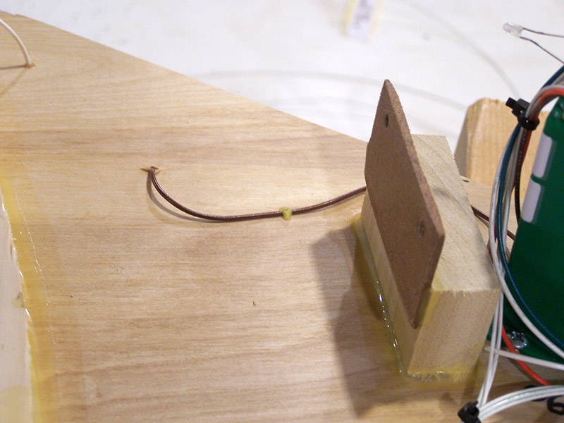
In a few spots there remained individual wires that because of their routing were not part of a bundle. A drop of wood glue was used to secure them in place. Wood glue doesn’t stick worth a darn to PVC wire insulation. But if it encapsulates the wire no adhesion is needed. I kept the glue thickness at a bare minimum across the wire so if by pure dumb luck a hole needs drilled directly above a glue drop I can easily pull the wire from the glue.
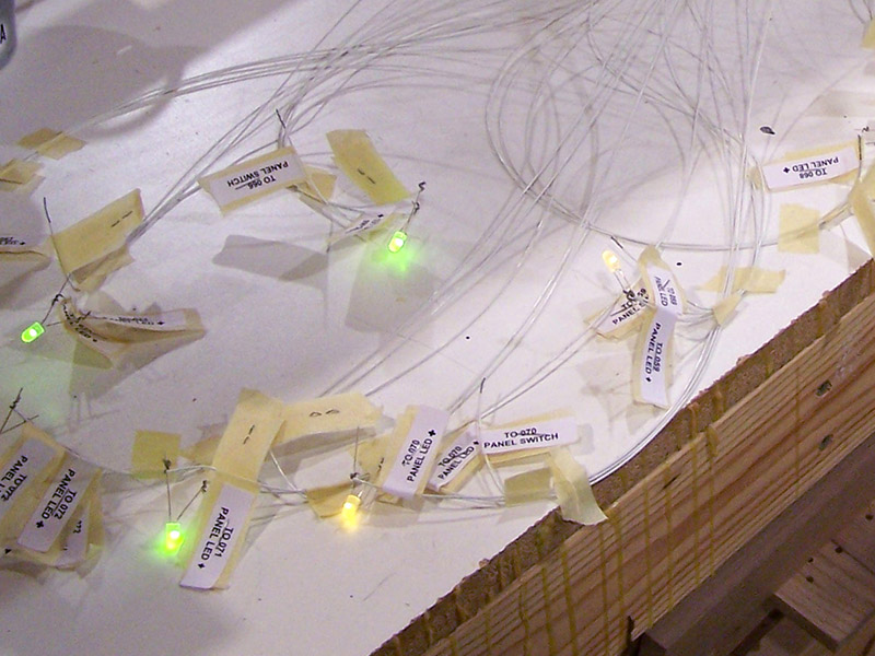
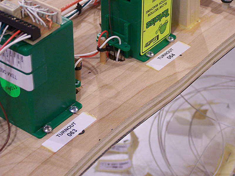
Throughout the entire wiring process I kept my meter handy to verify each wire was electrically connected as it was placed. I also attached LEDs to the panel wires as I went along to verify correct operation of the indicator connections. A Tortoise could be actuated by touching an accessory power lead to the corresponding switch wire. It was messy but served the purpose. The ability to operate the Tortoises was also needed to test proper operation of trains on the track once the module was flipped right side up.
The last step on the underside was to place labels on everything. While I keep a master schematic, it sure will be nice to not be forced to remember anything when working under the layout in the future. Everything is labeled to match the schematic. Again, not trusting label adhesive, I brushed a thin line of wood glue onto each label end.
Speaking of testing trains, I have that completed as well. This post is getting quite long so I’ll save it for the next post. I’ll close for now by officially pronouncing module #1 wiring finished, tested, and fully operational.


Simply astonishing! The dedication to stick to a common standard for everything like you have Alan is a testament to your ingenuity and exceptional planning abilities. Jas.