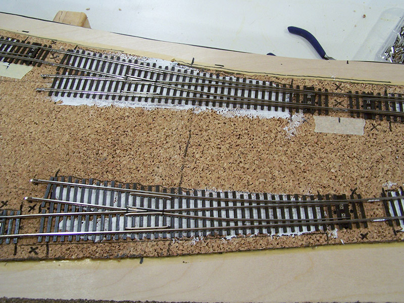
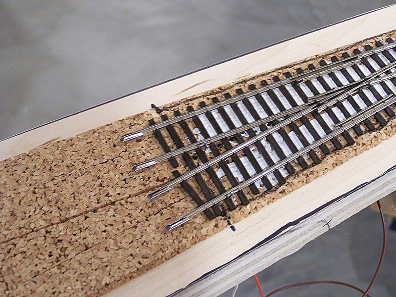
Caulk really holds track well! I had spread it really thin and had some concern that I may have spread it too thin. It was setting up very quickly during the spreading due to the thinness. Well, fear not. It has a fantastic grip today. Here is a picture of a typical application. There are more pictures in the gallery below.
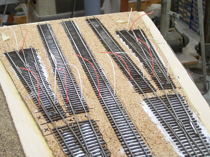
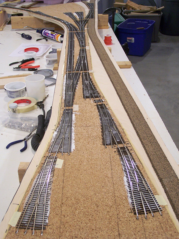
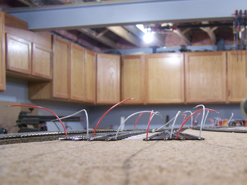
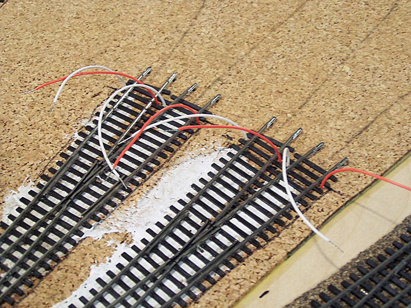
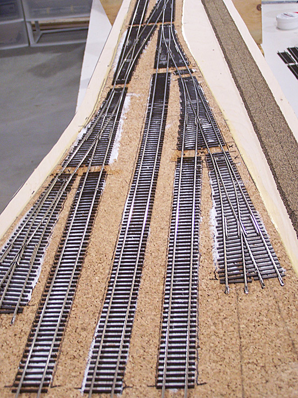
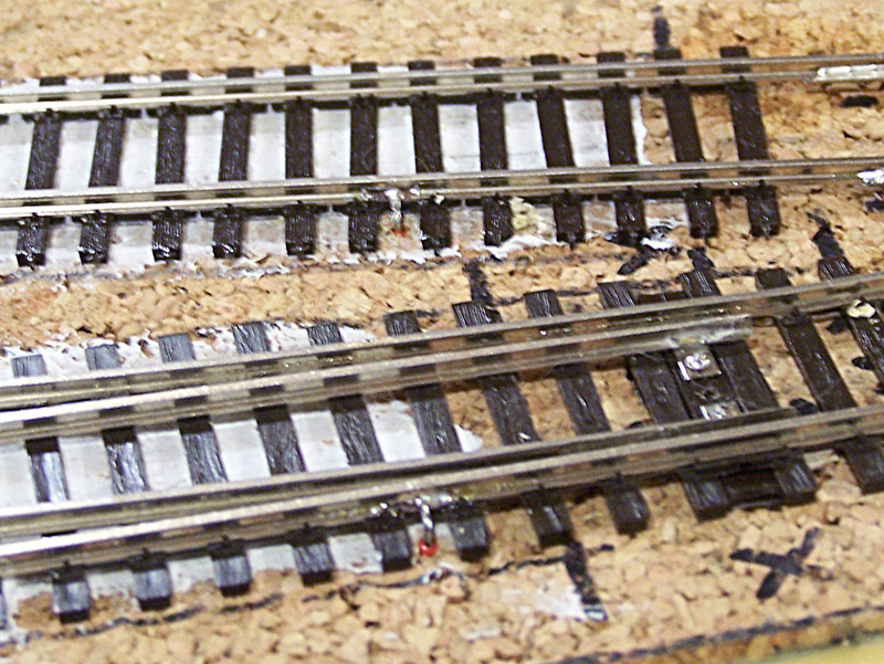
With the caulk dry the next step was to drop feeders. As I stood there looking at the track I thought there should be some logic to how many feeders there are and where they are placed. Ultimately I decided 3′ would be the target distance between feeders on the same rail and any rail that relies on the built in shunts in the switches would also get a feeder thus making the switch shunts redundant. 3/32″ drill in hand I set about drilling holes along the track making certain no feeder drops were placed over a benchwork cross member. 12″ long pieces of 24AWG stranded wire were cut and inserted into the holes as I went along. Orange is the positive rail, white the negative, and brown for frogs. The feeders for the frogs are on the backside away from the aisle to help hide them.
Next, feeders were soldered to the rails and frogs. I had read so much about people melting ties during feeder soldering I have to say I was a bit apprehensive going in. Well, that faded fast. Nothing to it. I suspect the folks that melt ties are too slow in their motions. With a good hot iron and a little flux on the rail it was a piece of cake to solder without melting anything.
I first applied a tiny bit of solder to the rail. Then I tinned the feeder wire. Once the wire was in place all that was required was to press the two together with the iron. The thin pre-tinned stranded wire joins with the rail solder instantly when the iron touches. A little cleaning with IPA on a cotton swab to remove the flux and finished.
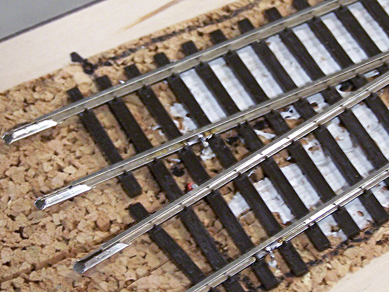
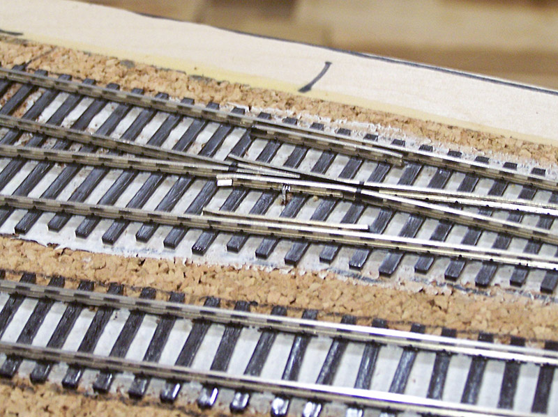
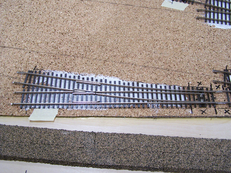
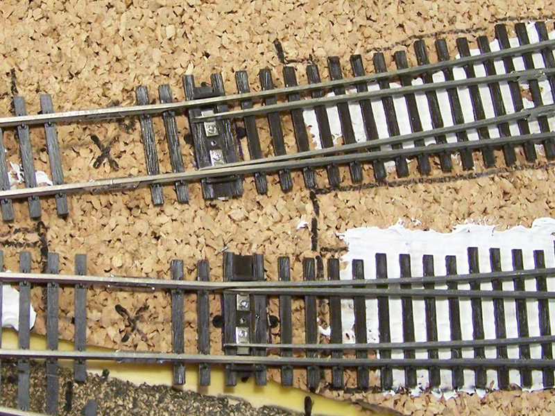
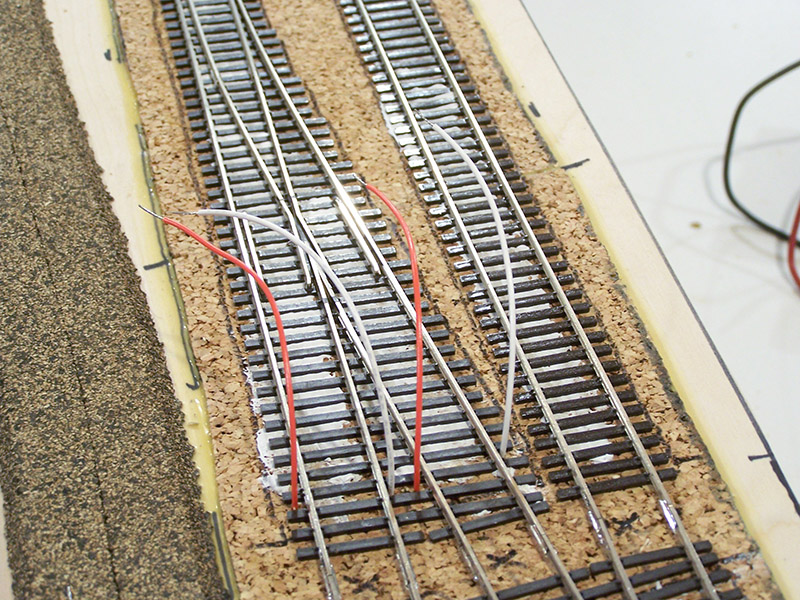
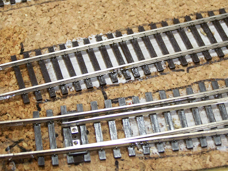
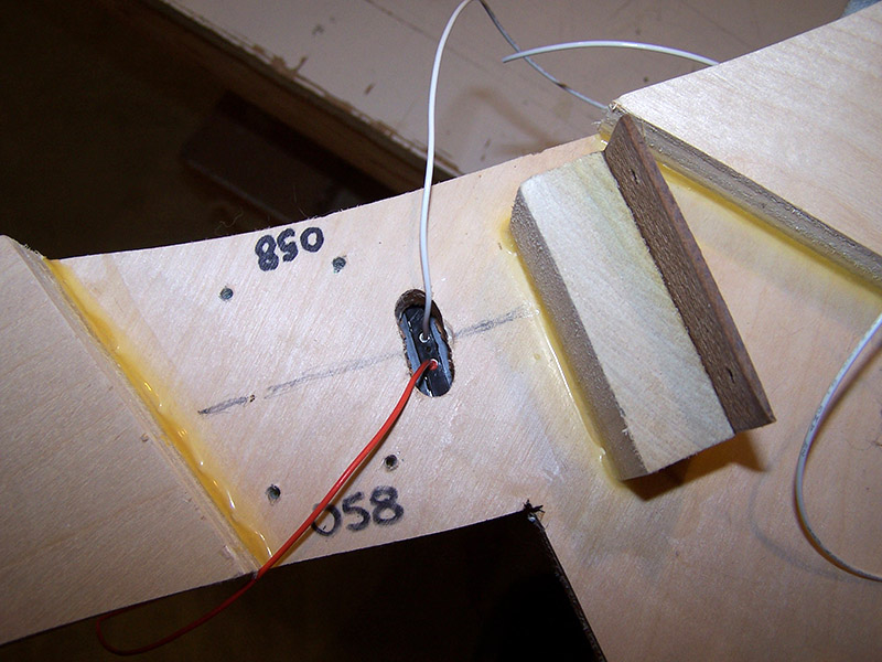
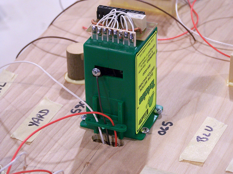
The switch point rails received a different method. It is very common in the hobby for people to solder little jumpers across the hinge of the points. I did not do that. Instead I soldered feeders inside the rivets that hold the points to the throwbar. Solves two problems at the same time – the rivets had to be filled anyway so as to disguise the fact they are big rivets and it provided a totally invisible way of powering the points. The feeders come up through the Tortoise slot and are held away from the Tortoise wire by the fulcrum piece. Cool, huh?

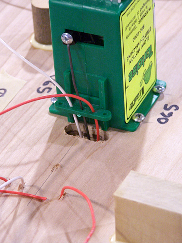
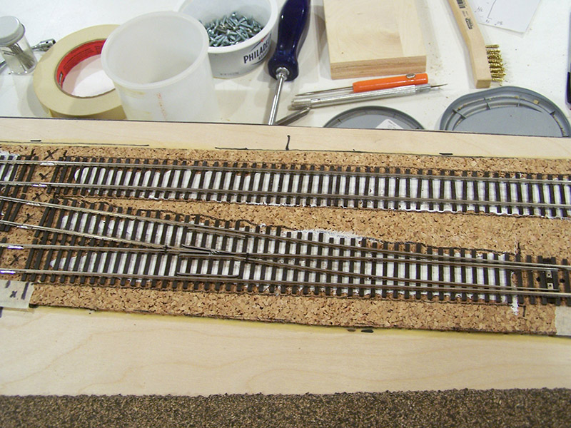
Speaking of Tortoises… I ended up replacing the throw wire with a heavier gauge piano wire. 0.047″ instead of the original 0.025″ to be specific. While the 0.025″ wire did move the points just fine I wasn’t pleased with the amount of tension it applied holding the point rail against the stock rail. It was way too easy to flick the point away. In the perfect world where every wheel truck rolls perfectly in alignment there should be no real need for much tension. Sadly, I don’t live in a perfect world. Far from it. So I wanted a little extra insurance from wheels potentially picking the points. Hence the heavier wire. The Tortoise lever, fulcrum, and switch throwbar had to be drilled to accommodate the larger wire.
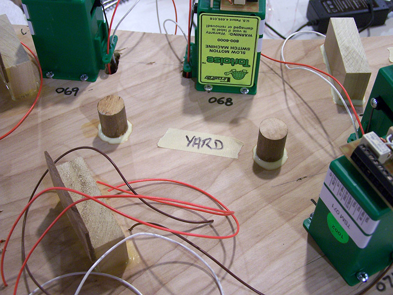
I kept adjusting (bending) the wire position during Tortoise final installation until there was the same amount of Tortoise travel in both directions. In other words, the switch throwbar was centered when the Tortoise mechanism was midway between throw end points. The fulcrum was then moved up until there was a slight wire pre-load at the end of the Tortoise travel. As you might imagine the track on 3/16″ thick cork (mainline) required a higher fulcrum setting than track on 1/8″ thick cork (yard). It took me the better part of a day to mount and adjust all of the Tortoises on the module. It was fun at first but I must admit adjusting Tortoise wires did get a bit tedious after a while.
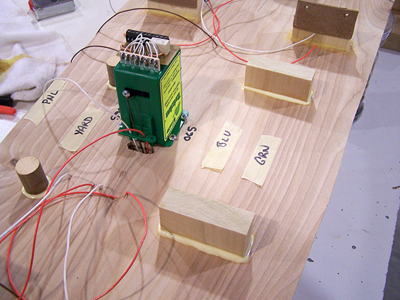
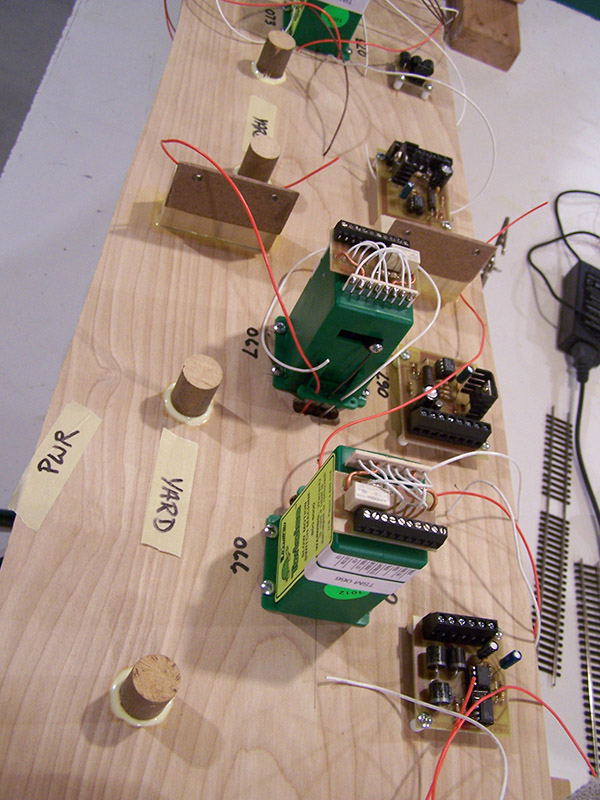
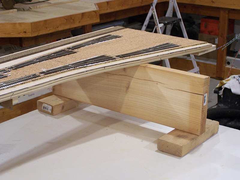
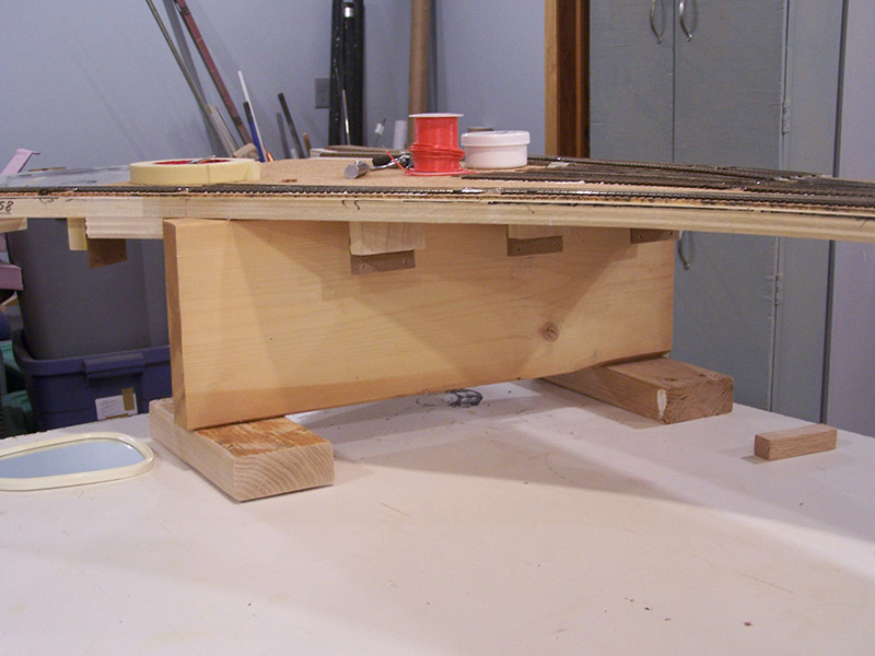
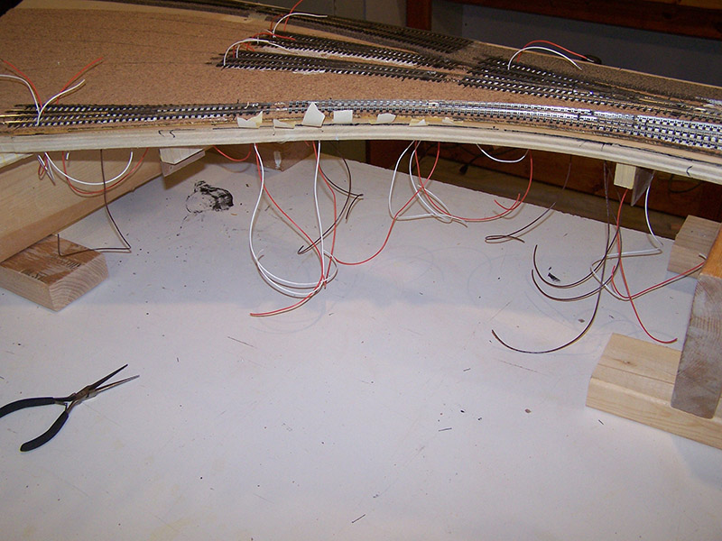
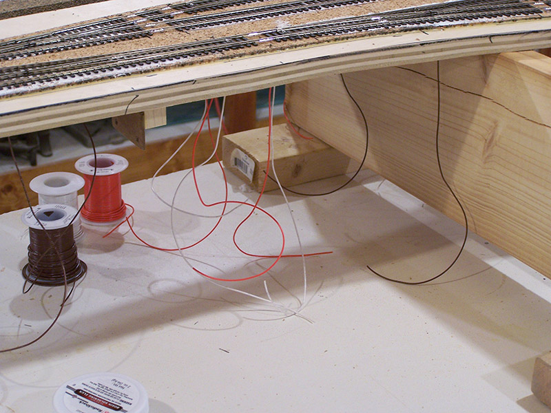
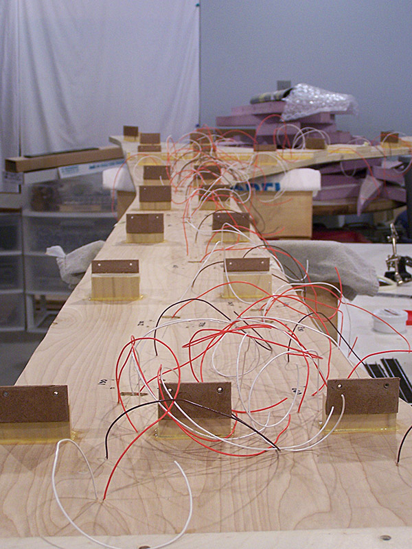
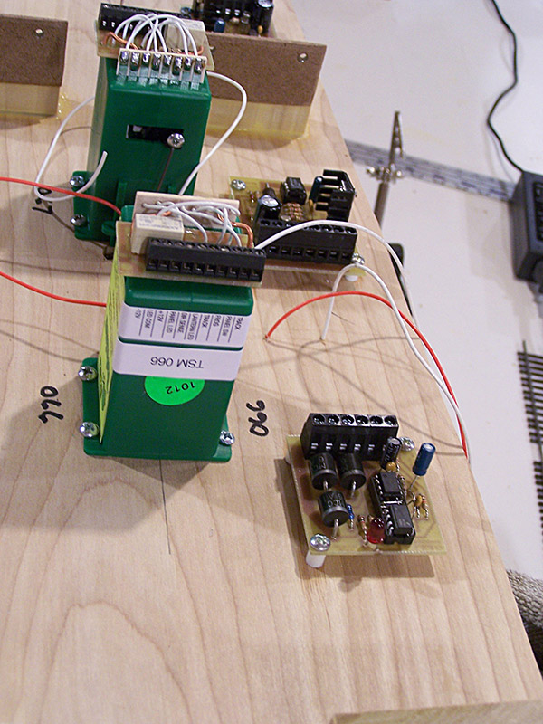
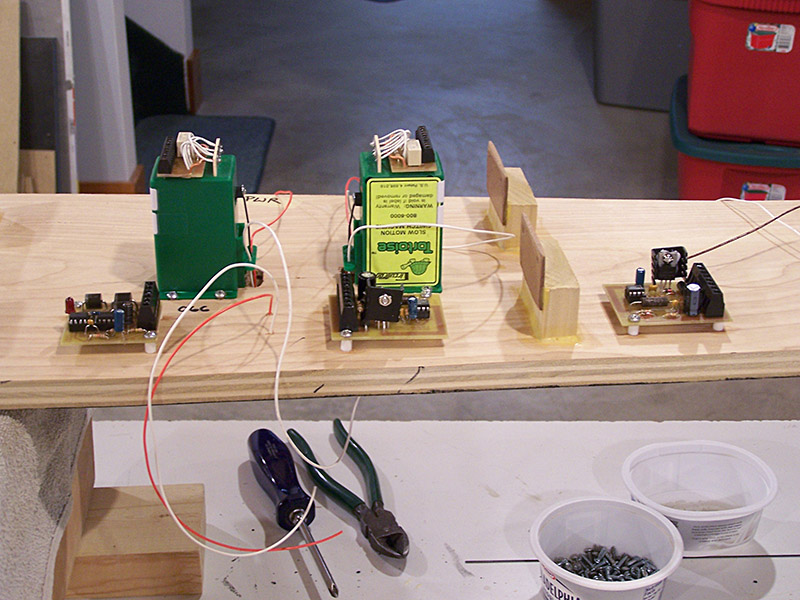
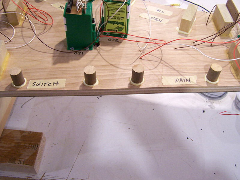
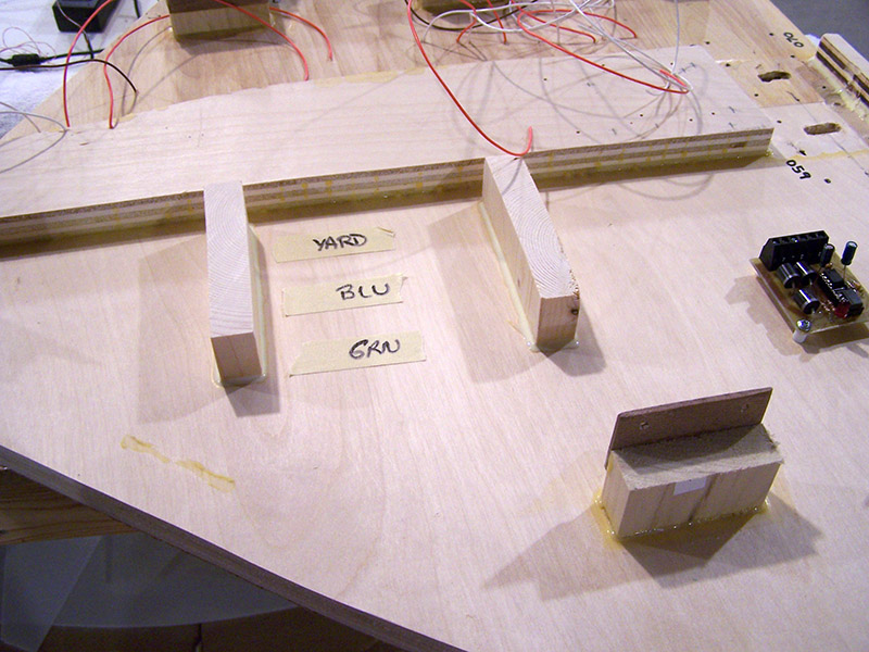
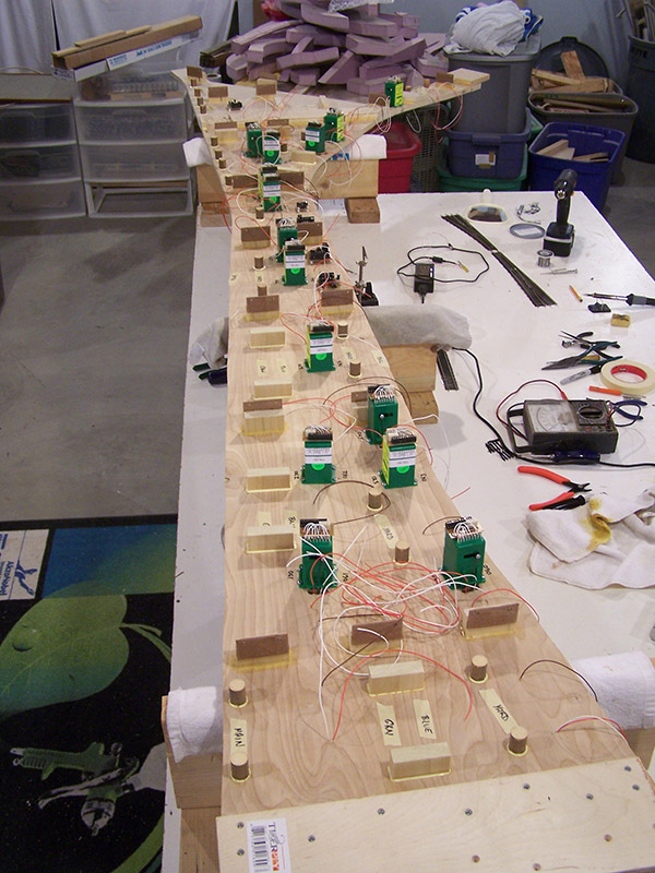
Next came mounting the electronics and routing the power buses on the module. I used masking tape to mark where tie points would be located keeping in mind I will be upside down looking up when I connect future wires. Things like space to get my fingers in to wrap wire and accessibility with the soldering iron were considerations as I selected locations. I also want to minimize wire congestion in any one spot. I ended up moving the tape pieces quite a few times before I was satisfied with the routing. Just like utility lines, my power buses will be supported by “telephone poles”. I cut 3/4″ dowel into a bucketful of 1″ tall pieces. I would have preferred 1/2″ dowel but this is a case of use what you have. For reasons I have long forgotten I have a lot of 3/4″ dowel. The final work today was to glue them in place so wire can be strung across them tomorrow.


Hey Alan, one little piece of advice with the Shinohara’s that you may want to consider implementing before you move on? Is ensuring that there is no cork roadbed underneath the switch point blocks, I have found that when gunk (usually after track cleaning & dust) gets underneath it it can sort of bind the movement a little.
I simple cut out the section with an Exacto knife to remove the entire length and width from underneath it, although with your thicker throw wire it might not be such an issue.
Jas.
PS: Love the idea of soldering the point wires to the rivets and filling them up at the same time, brilliant!
Thanks for the tip Jas. There is actually very little cork left under the throwbar due to the size of slot I make. But there is still some. I haven’t noticed any binding but then again no crud has built up either. It might be tricky to further clean out cork from these turnouts as they are glued down. But I will do that from here on out.
Alan,
I am amazed by your craftsmanship and ingenuity. Is this your first layout or did you build a smaller, chainsaw type of layout first?
Your electronic design work is equally impressive…and I’m an EE…and i studied at the University of Akron and so I am familiar with some of the areas you are modeling.
Best wishes and keep up the good work!
Hi John. Thank you for your compliment.
This is the first railroad I have built since I was a youngster. Back then it was Atlas sectional track and Tyco equipment. Big difference to today, eh? 🙂
Wow, you make it look like you have been doing this for years!
My start was with my father’s late 1940/1950’s Lionel trains. Things sure have changed–especially in the electronics area. Im really looking forward to seeing how RailPro works for you.
I don’t have the space or time for a big layout and so I am just trying to do some little things–like weathering some cars, maybe making some dioramas. Im also doing a lot of historical research–which is fun–and making decisions on what I would like to model. It will be something from the Cleveland area, I just haven’t decided what.
Again, thanks for sharing your work, it is really interesting and motivational.
Best wishes to you and your family for a wonderful Christmas and a Happy and healthy 2015.
Great post as always Alan. I find that a variable temperature soldering iron is THE BEST way to solder feeders to the rails. Some very important things to mention when soldering.
ALWAYS make sure both the rail and wire are clean and I don’t mean what the flux will do. I have some older track I have been working with and thought that just flux would be enough to make a solder joint. It was but it takes a lot more heat to get the solder to make the joint. The heat has to first get through/remove (with the help from the flux) the corrosion then it can start to clean the rail/wire properly. If you make sure both are clean the soldering is quick and effortless.