Soldering rails is all finished. Pleased with the results. Next steps – fit the Tortoise machines and glue the track in place.
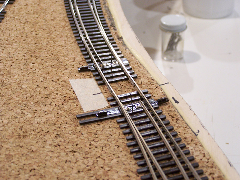
At each switch I slid the throwbar over and made an ink marker dot on the roadbed at the end of the throwbar. This shows me how wide I can make the Tortoise rod slot without it being exposed. I did this at each switch. Another pair of dots were made on each side of the throwbar in the center just to give me additional reference points when cutting. In addition, I drilled a few real small holes on the track center line a few inches away from the slot. These little holes will guide me in getting the Tortoise machine rod movement parallel with the throwbar movement. I then removed the track assembly. Measuring 3/16″ in from the inside edge of each mark I drilled a 5/16″ hole. A jig saw with a narrow blade was used to cut the sides between each hole. Finally, a router with a 1/4″ straight cut bit was used to refine the slot and to make sure the slot walls were perpendicular to the roadbed surface. The result looks like this:
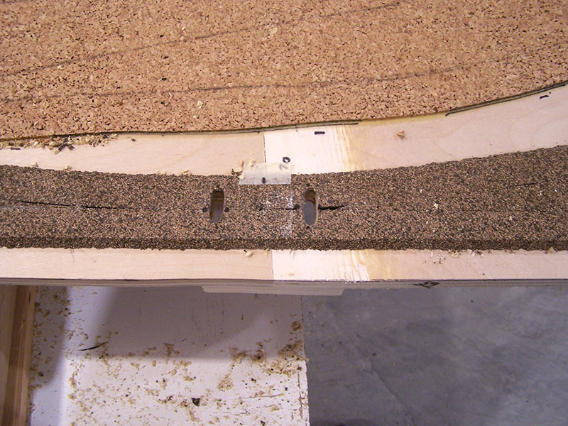
You may be wondering why such a wide slot is needed. Most people just drill a 3/8″ hole. The reason is because I am going to route the points connections through this slot also. It will be clear in the next post.
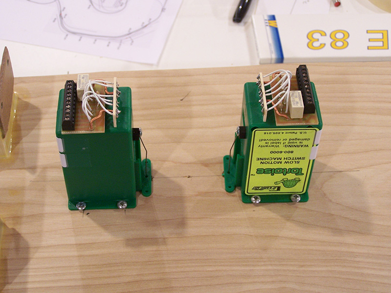
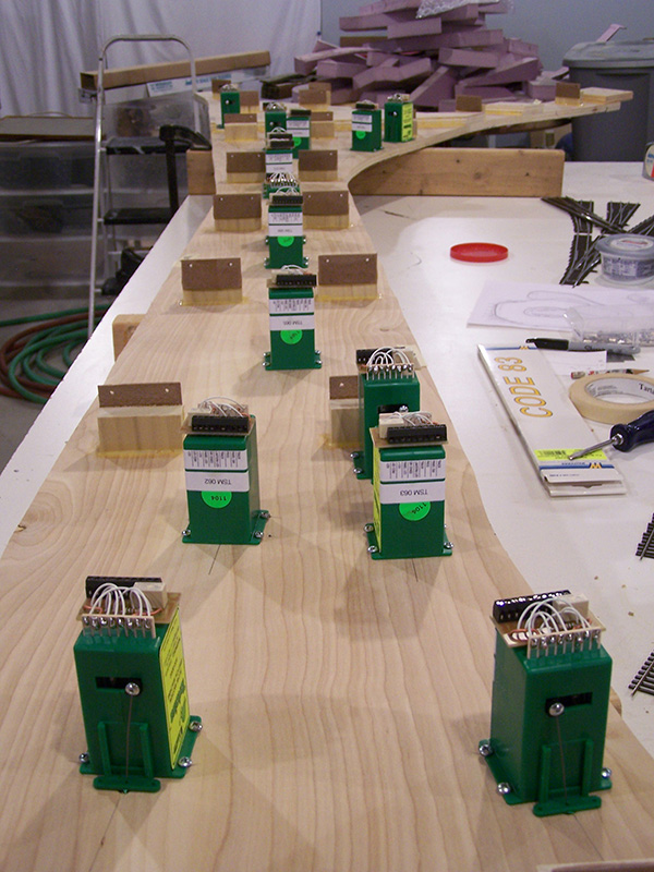
Once all of the slots were cut I flipped the module over and began locating Tortoises. As it turns out the little green fulcrum piece that comes with a Tortoise is the perfect size and shape to align with my slots making Tortoise positioning a breeze. A pencil line was drawn between the little marker holes drilled earlier. I used a Tortoise itself for a template to mark drill points for each location making sure the Tortoise was centered on the pencil line. There is a molding seam on the Tortoise case that made a natural alignment point. The identifying number of each Tortoise machine was added on both sides of where the machine mounts in the event at a later date I am under the layout troubleshooting. I’ll be able to see the number regardless of which side of the Tortoise I am on.

Tortoise assembly of the rod and fulcrum was per the Tortoise instructions using the supplied rod. The instructions called for #4 mounting screws but I substituted #6. They work fine with no alteration to the Tortoise mounting base and, unlike #4 screws, a regular #2 Phillips fits them. I positioned the fulcrum tight against the sub-roadbed.
The module was returned to right side up and the track assembly put back in place feeding each Tortoise wire through the respective throwbar as the track assembly was laid down. This was done to verify the Tortoises were in the correct location, the wire had ample clearance, and everything moved freely. A few slots required a little touch-up with the router bit.
With everything looking good it was time to put the track down permanently. The track assembly was once again removed from the module and the Tortoises dismounted.
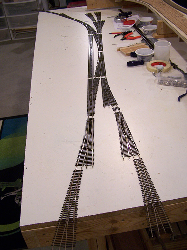
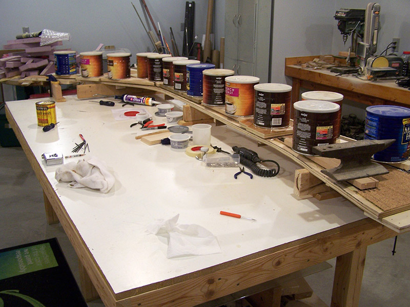
A bead of nothing special painters latex caulk was spread down the track center line making sure to stay clear of the Tortoise slot areas and then the track assembly carefully placed into position. After a quick inspection to make sure there were no caulk blobs or squeeze up between ties I weighted everything with my trusty concrete coffee cans. Tomorrow I’ll pull the weights and boards to see if it worked. Cross your fingers!

[…] preparing Tortoise throw rod slots accordingly. Since the process represents an evolution from the originally described process and is my new standard procedure a diagram is in […]