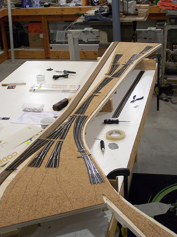
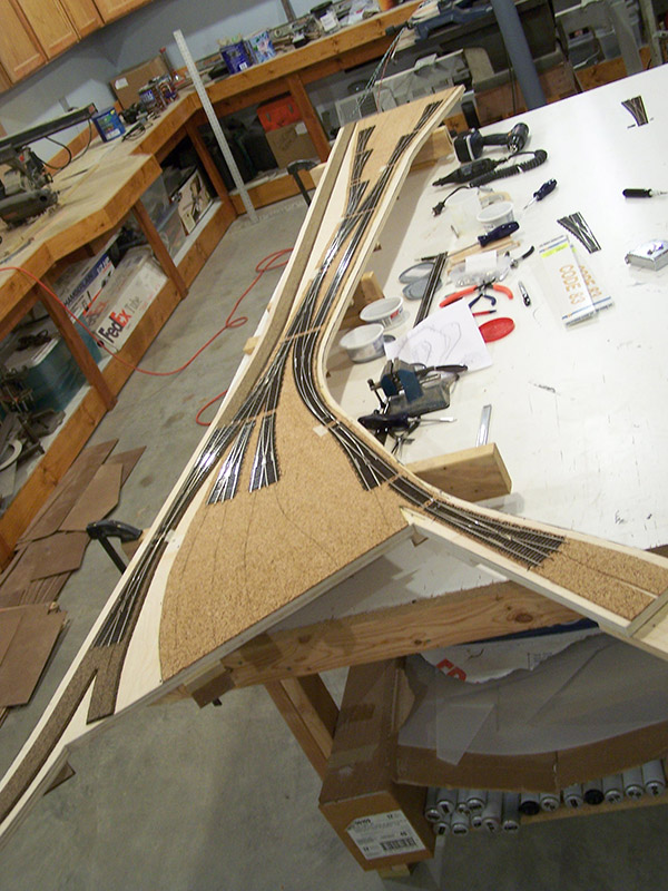
The glue fillets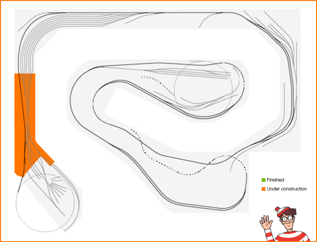 around the risers are dry and the module has been flipped right side up. Brittain Yard, specifically the yard throat, was chosen as the first module because it is the most densely packed area of switches and wiring. There is another reason. Much of the yard throat is end-to-end switches. This arrangement affords me an opportunity to see how accurately the track plan transferred from paper printout to pencil lines on the sub-roadbed. Will the switches line up with the pencil marks when they are connected together?
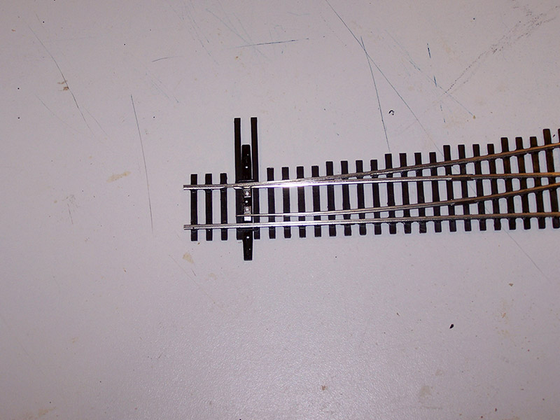
A little bit of switch modification was first necessary to find out. The throwbar and headblocks interfered with adjacent switches. The headblocks are purely decorative and the extended throwbars are not needed since my Tortoises connect through the hole in the center. (BTW a hole in the center of the throwbar seems like a hit-or-miss feature on Walthers Shinohara track. Same part number – some switches have it, some don’t. A 1.1mm drill remedies the situation.) A chisel blade easily slices the throwbar and/or headblocks in one cut. Later, the headblocks and a switchstand will be placed as appropriate. To keep the extended throwbar from interfering with the final headblocks I first slide the points all the way over and trim the throwbar on the opposite side. Slide the points back and do the same on the far side. Now my throwbar never extends beyond the ties.
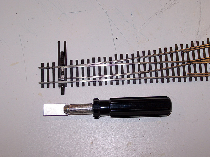
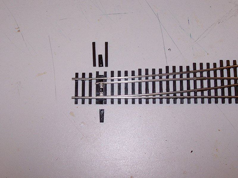
Initially, I modified only the switches with interference problems on this first fit up. I think it is going to become my standard practice to cut the protruding plastic from the switch as soon as I take it out of the box. Same with trimming off the last tie for rail joiner clearance.
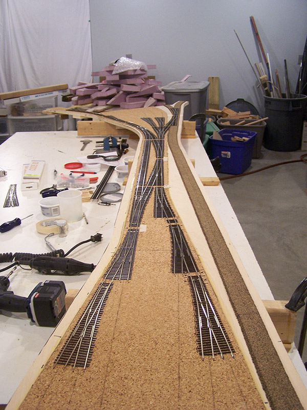
A few rail joiners later sees the yard throat assembled and laid in place. I am happy to report the pencil lines and cork centers line up well. Certainly close enough to give me confidence the track will lay as planned. Time to break out the flex track.

I placed the flextrack needed to interconnect the switches. The flextrack pieces that extend to the end of the module will be placed when the corresponding “B” plate at each end is fitted.
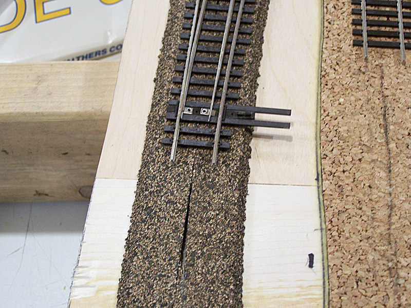
Once the track was adjusted to its final position I placed 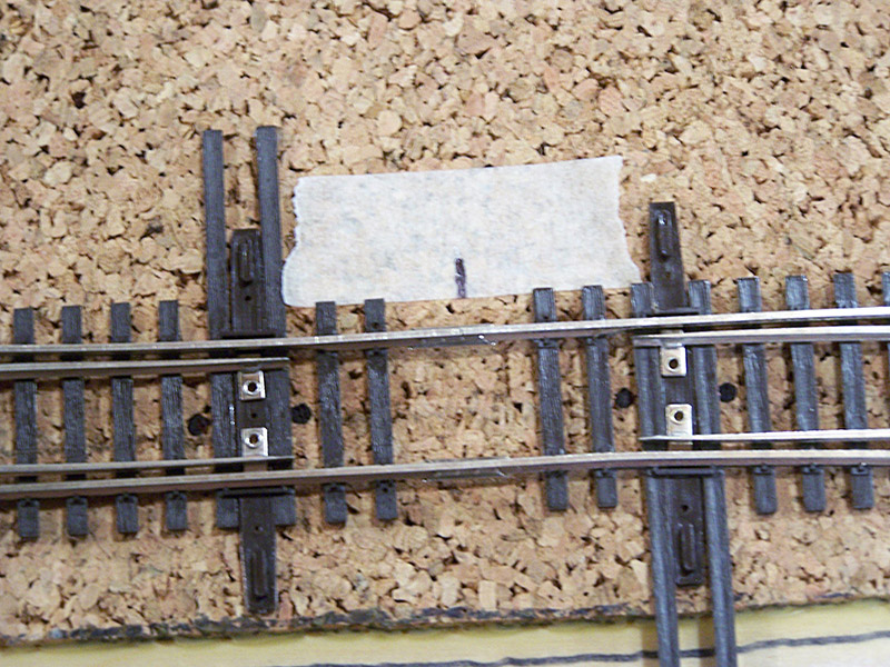 a few strategically located pieces of masking tape so the edge of the tape aligned with the end of the ties. A mark was placed indicating rail joint. These pieces of tape will help me align to the same position when the trackwork is re-installed. Another nice feature of assembling on the workbench instead of the layout is the ability to sight down the track to make sure everything is straight and properly aligned.
Satisfied the assembly was in the right position I decided to solder it together into one giant assembly. This is my first time soldering rail joiners. I have soldered many things in my life but never train track. First time for everything, right? Heat up the 40W iron and here we go.
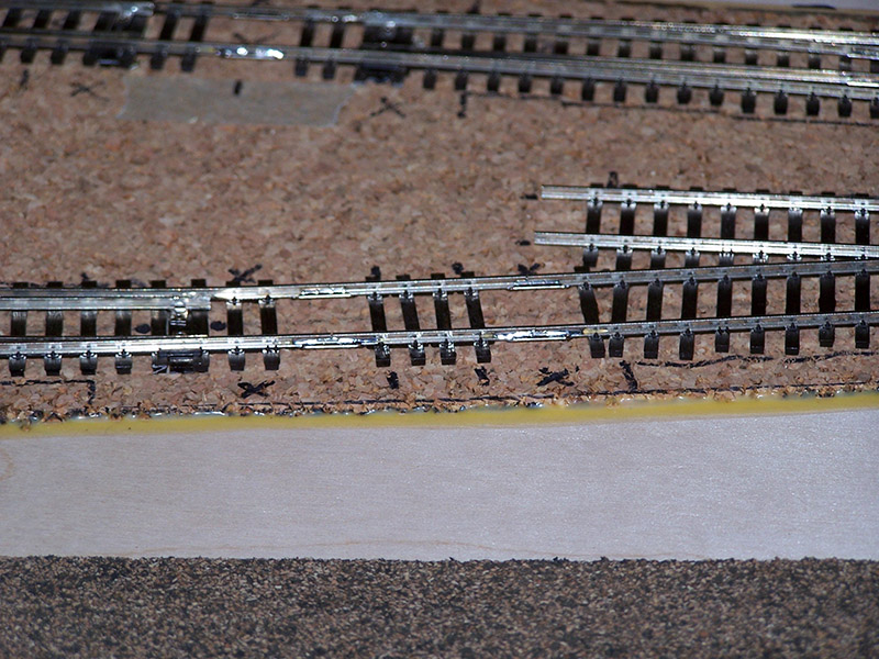
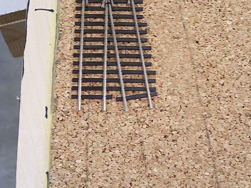
I had hoped that I would be able to get the solder to sweat in from the end of the joiner around the rail so there would be practically no visible solder. As you can see in the picture that didn’t happen. Regardless of where I positioned my iron I could not pull the solder sufficiently. The solder always climbed onto the outside of the joiner somewhat. At least the solder sheeted nicely. The bright solder reflection from the camera flash make the joints look far more blobby than they really are. The solder actually lays quite nice on the rail and joiner. I went to clean up the joints a bit more with desoldering braid only to find out my braid is way, way too big for the job. I’ll have to get a roll of small braid to finish the job. Meanwhile, I’ll keep trying different techniques to minimize the amount of visible solder. If anyone has any tips on soldering joiners I am all ears. For now these will be just fine by me once they are painted and weathered.
Soldering model rails is much easier than welding the real thing!
Now if you will excuse me, I have quite a few solder joints to make. Thanks for following along.

Good to see that the Shinohara’s are aligning with the original track plan. The yard throat is coming along nicely too, can’t wait to see that first module finished.
Great job Alan, love reading the updates and your powering along too!
Jas…
I have found that using .032 dia. solid solder with a liquid flux allows the solder to flow very nicely. Supersafe Superior #30 Soft Solder Gel from H&N Electronics California City, CA 93505 is where I purchase soldering material and get information. Very good prices and very informative. My technique for joiners is to use a small brush to apply the flux and then apply the solder to a hot iron and then to the rail joiner. Usually enough solder flows from the iron to the joiner to flow underneath and make a very smooth joint.
Thanks for the tip Nate. As a follow-up, practice makes perfect. I am getting very nice looking joints now by laying the iron against the joiner and rail near, but not at, the end of the joiner. Touching the solder to the end of the joiner sucks just enough solder towards the heat to make a nice smooth minimal solder connection. I’ll check out the solder gel you mention.