As mentioned in the previous post, I am building a sensing system such that on a fascia panel you can see your train position and movement in the helix. There are no doubt any number of ways to go about this but I choose bouncing IR light off the rolling stock onto an IR detector. I selected this method for a couple reasons. First, since the emitter and detector can sit side-by-side all the sensor components can be mounted on the inside radius of the helix. That makes for easy access. The helix sits in a corner against two walls and the top loop is within the upper deck benchwork. A good portion of the outer radius won’t be readily accessible when the helix is in position. A break beam system would have required components on the outer radius rendering them difficult to service should the need arise. A vertical break beam system would be even more difficult to service with the emitters and detectors embedded between the rails and so little loop to loop clearance to work within. The second reason, and the more important of the two to me, is I am trying to build from parts on hand as much as possible. I just happen to have a ton of 940nm IR photodiodes and emitters.
Here is the circuit, in its most basic form, from which I am starting.
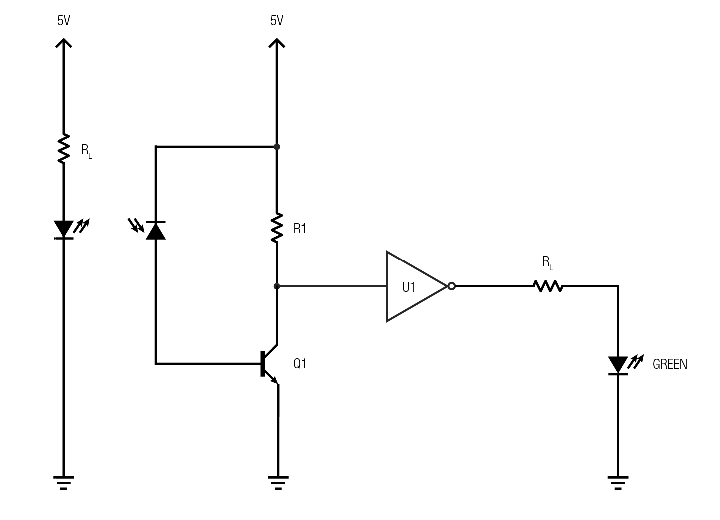
On the left is the IR LED and its current limiting resistor RL. The IR light bounces off the rolling stock onto the photodiode sitting next to the LED. Notice the photodiode is installed backwards. If it were installed in normal polarity it would conduct continuously essentially becoming just a wire. Diodes have reverse leakage current i.e. the tiny amount of current that can pass backwards through the diode. This circuit takes advantage of the reverse leakage and hence why the diode is reverse biased in the schematic. The amount of reverse current is very small on the order of a micro amp or less when light hits the diode. That’s where transistor Q1 comes into play. The transistor amplifies the current from the diode so we can do something useful with it.
U1 is a CMOS inverter (NOT gate), the simplest of all logic gates. If 5V is present on the input then ground is present on the output. If ground is present on the input then 5V is present on the output. The output is always opposite of the input. Inverters are most commonly used in digital electronics with 5V being a logical “1” or TRUE and ground being a logical “0” or FALSE. That’s exactly what I need. TRUE if a train is present, FALSE if a train is not. Inverters come 4 and 6 to a package. I happen to have a bunch of very old CD4584 which is a six gate package.

CMOS logic circuits require very sharp, fast, rise and fall times on their inputs. A Schmitt input is an exception to this rule. Not only can Schmitt inputs tolerate slow rise and fall times they also have a dead band in the middle as a result of having two switching thresholds instead of just one. On a 5V system, a rising voltage from ground will not trigger the gate until it rises to 2.7V. A falling voltage from 5V will not trigger the gate until it falls to 2.1V. There is 0.6V hysteresis where nothing changes. This cleans up the sloppy slow rise and fall times the photodiode will produce as trains pass. CD4584 is a Schmitt input inverter. Below is a visual showing what happens when a varying signal is applied to a regular gate and to a Schmitt input gate.
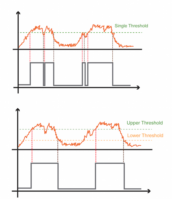
an-introduction-to-schmitt-triggers-otto-schmitt
R1 and Q1 are arranged as a voltage divider across the input of U1. When there is no light hitting the photodiode no reverse current flows and transistor Q1 is turned off essentially becoming an open switch. The input of U1 is connected to 5V via R1 and since inputs of CMOS gates draw such small amount of current there is almost no voltage drop across R1. The input of U1 sees 5V or very nearly so. The high on input results in a low on output causing the green LED to be extinguished. When light falls on the photodiode, transistor Q1 amplifies the current and turns on creating a low resistance path to ground for the U1 input. Since the resistance across Q1 is now very low compared to the resistance of R1, the input of U1 sees ground or very nearly so. Ground on the input creates 5V on the output turning on the green LED.
We could hook the green LED directly to Q1, eliminating U1, but this causes a problem. The green LED brightness would be proportional to the current through the photodiode. Different color and shape rolling stock have different reflective qualities. That wouldn’t look good on the panel. By using U1 and its Schmitt triggering we get full-on or full-off green LED on the panel regardless of how much the rolling stock reflects.
There you have it, the basic circuit and how it works. Next is optimize the circuit for real world use on the helix. I’ll dive into that in Part II.

Dear Alan. Thanks for explaining your thoughts in such a clear way. It is always inspiring to read your writing.
Regards from Switzerland, Adrian