When we last saw our hero he had just finished an arduous sanding adventure which left him with sore fingers and nearly no fingerprints left.
The fingerprints are back and the fingers recovered. Time to turn the bare wood pieces into something pretty.
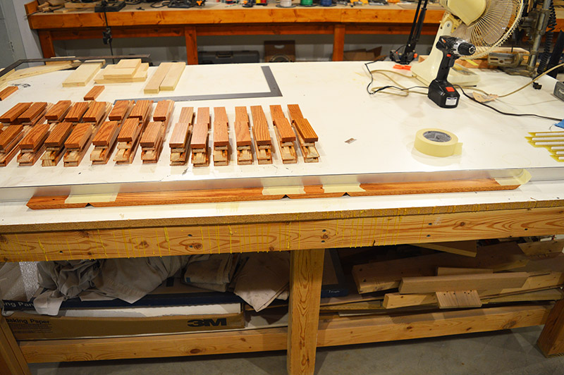
After securing the enclosure pieces to chunks of 2×4 with rolled masking tape and some on nails through pieces of plywood I set about staining. A fast wipe coat of Golden Oak stain followed by a dry-in-place coat of Golden Pecan stain yields a rich color I call Honey Oak. This same stain combination is used throughout our house from doors and trim to furniture. After the stain dried overnight I then applied 4 coats of oil polyurethane satin clear with a 2-3 hour dry time between coats. This heavy clearcoat film gave me extra assurance I wouldn’t sand through on the edges. I let the pieces dry for at least 2 days, some much longer, to make sure the clear would sand nicely without balling up on the sandpaper. After flat sanding out the raised grain and dust nibs I applied 2 more final coats of polyurethane.
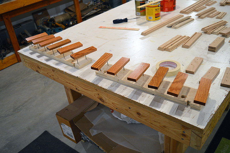
Here is a batch that has stain and first coats of clear.
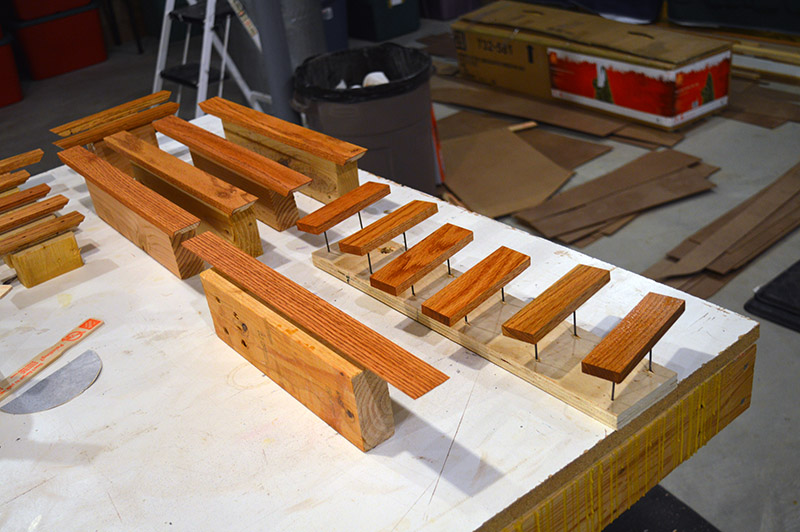
Same batch with sanded clear awaiting cleaning and final clear application.

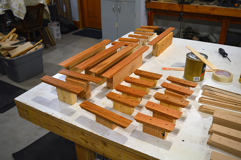
And then with final clear applied.
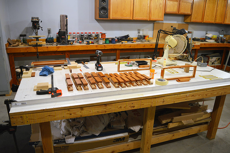
Finally, all pieces were left to thoroughly dry for over a week. Masking tape will be applied during assembly so I wanted to make sure there would be no tape tracking on the finish. These two tables are just some of the pieces. I had drying wood pieces sitting on virtually every horizontal surface in the basement!

While the wood pieces were drying I made a few connector boards.
My inkjet transparency print taped to glass of a picture frame. Actually three prints stacked one atop another. A single print doesn’t have sufficient opacity in the black ink to prevent penetration of UV from the lamp.
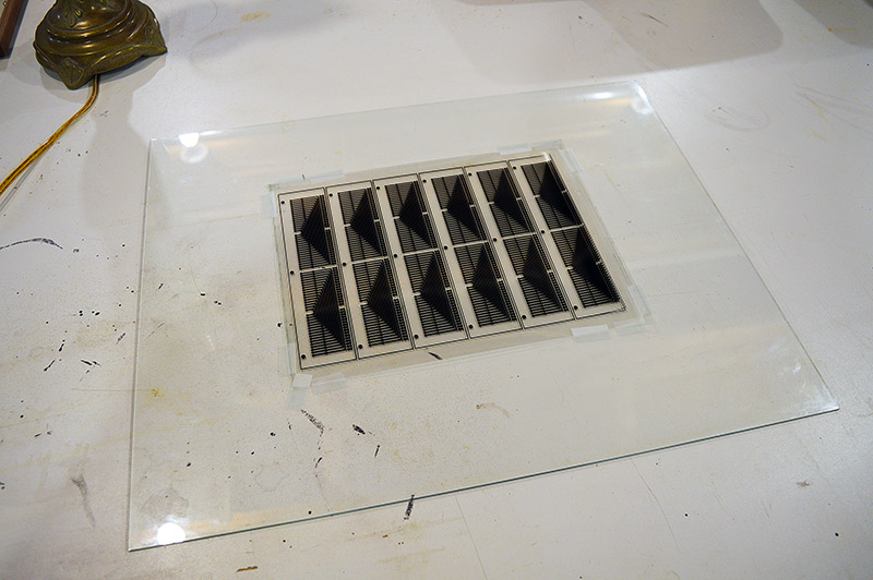
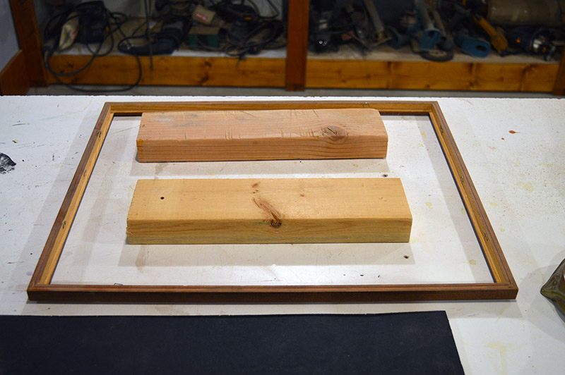
The picture frame with 2x4s underneath to put the glass weight directly on the inkjet print.
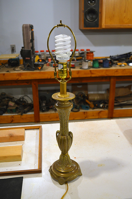
My hi-tech exposure luminary aka a 23w CFL in an old lamp.
My wife’s kitchen timer so I know how long to expose the board. 8 minutes BTW.

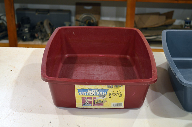
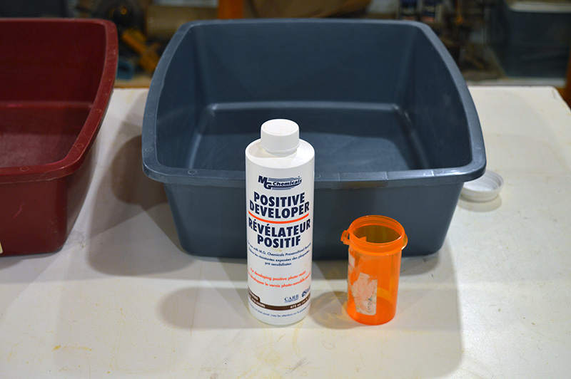
My etch pan sitting ready with the etch in the kitchen sink full of hot water.
The developer pan, developer, and measuring container ready to go. 1 part developer, 10 parts cold water.
Finally, the positive resist circuit boards.
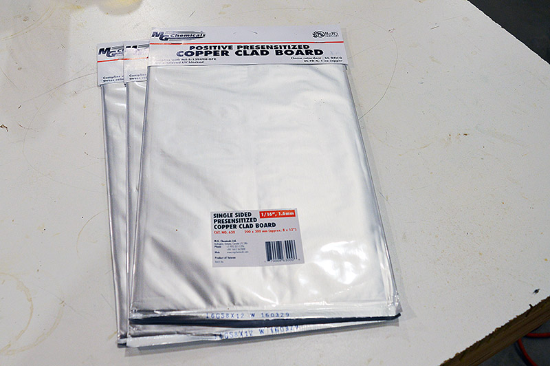
All set ready to go.
- Turn off the lights. Wait 30 seconds for the CFLs in the room to quit emitting UV.
- Turn on my drill press 40W incandescent lamp. Just enough light to see with no danger of UV radiating.
- Unpack the PCB. Peel away the protective film.
- Place the PCB face down centered over the inkjet print. Masking tape in place.
- Put the backing on the picture frame, flip over, and place on 2x4s.
- Turn on the CFL lamp for 8 minutes at about 10″ above the glass.
- Mix the developer solution.
- Take the PCB out of the picture frame and place in developer for 2-3 minutes until circuit appears.
- Wash off developer with flooding water. Turn the lights on.
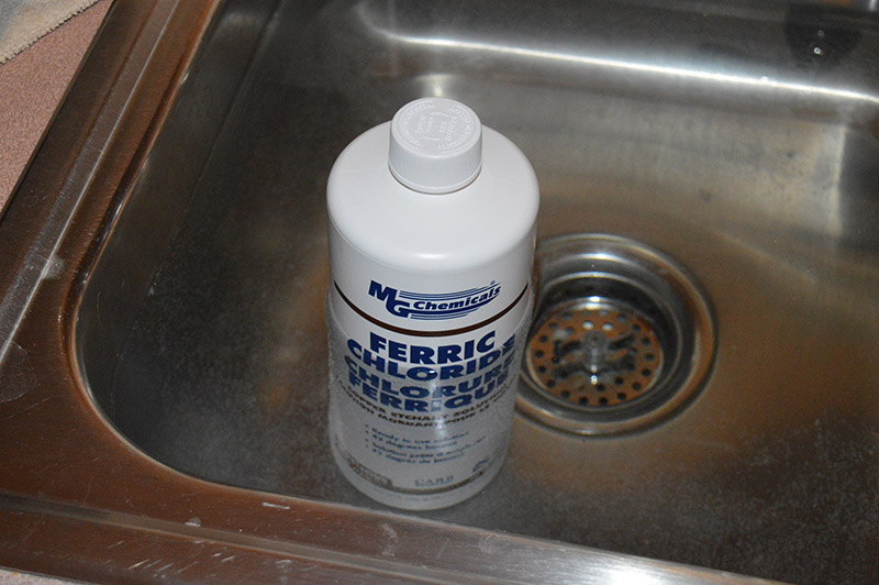
- Fill the etch tray with the hot ferric chloride and submerse the PCB. Slosh back and forth until all exposed copper is removed – about 20 minutes.
- Rinse off etch with flooding water.
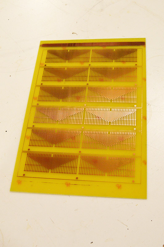
- Presto! Circuit boards.
Individual boards cut and trimmed on the disc sander.

Next comes the drilling. 0.030″ holes for the discrete components, 0.040″ holes for the connector strips. Man, there are a lot of holes in each board. Drilling, drilling, drilling.
Lastly, test fitting of the connector strips. These have 16 pins spaced 0.100″ apart so drilling accuracy has to be good.

I made six initial connector boards (one complete 200mm x 300mm blank PCB) to make sure everything works well before etching the whole batch of boards. Before I do more etching it is time to get back to enclosure assembly. The pieces have had plenty of dry time.
I set up my own little assembly line for this operation. I can keep three assemblies in various states of progress at the same time.
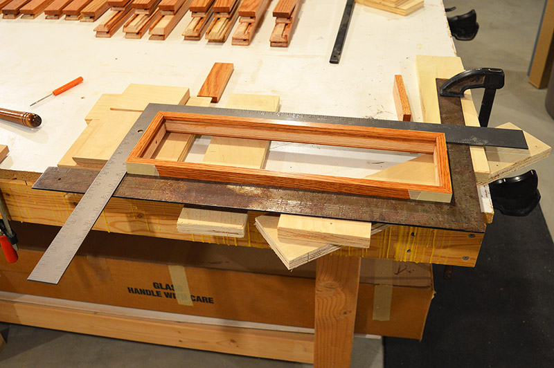
To start, I masking tape together all four sides lengthwise while holding them tight against a straightedge clamped to the bench.
Flip the taped assembly over and spread glue in the two joints at either end of the top panel. The bottom panel is later screwed in place hence no glue on it. I didn’t take a picture because you have to work really fast so the glue doesn’t skin. It’s winter here and the furnace drives the humidity real low in the house. Wood glue skins fast in these conditions.
Fold the assembly into a rectangle and place between a pair of framing squares to make sure we have a rectangle, not a parallelogram! I leave it here for a couple hours so the glue dries solid.
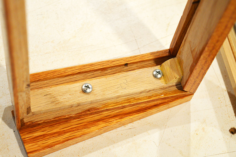
After initial gluing, I set reinforcing corner blocks in place at each end of the top panel.

Next, two circuit board support posts are added. These are here to prevent the circuit board from flexing when pushing in the wire connector plugs.

The bottom panel and corresponding side panels are pilot drilled 5/64″ for a #4 wood screw. This is done while the masking tape is still in place holding the top panel in position. Masking tape is then removed and the bottom panel shank drilled 7/64″ and countersunk. The bottom panel is then screwed onto the assembly. Sorry, forgot to take a photo of this step.
Lastly, the side blocks are attached with #8 x 7/8″ sheet metal screws in the holes that were drilled earlier with the jig.
The final result:
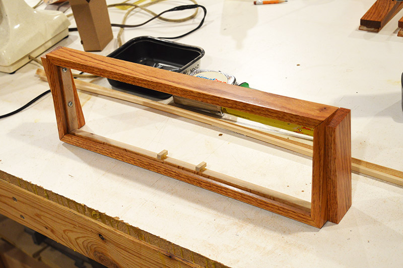
Use your imagination and place this inside the new enclosure.
Cool, huh?
On the next post I should have 16 finished enclosures to show you. Until next time…

most incredible work Alan
Cool, indeed. Yet another of your completely over the top processes demonstrating your abilities and attention to details in different disciplines. Thanks again for taking the time to document your journey. Truly inspirational.
what David said! Inspiring work, indeed!
Thanks for the compliments guys.