This is a mid-process post about making the wooden panel enclosures. I originally intended to finish the enclosures before creating the post but my progress has been so intermittent lately it is causing a long interval between posts. Didn’t want everyone to think I fell off the planet.
To begin the fun I purchased several four foot sticks of 1½ x ½ red oak at Home Depot SKU 226935.
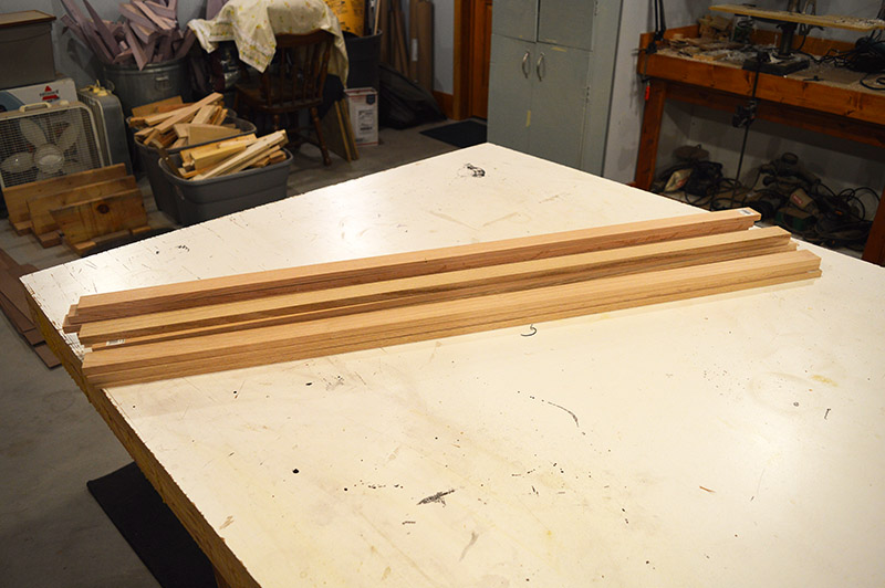
A ¼”W x 3/16″D face panel groove was cut the full length of each board.
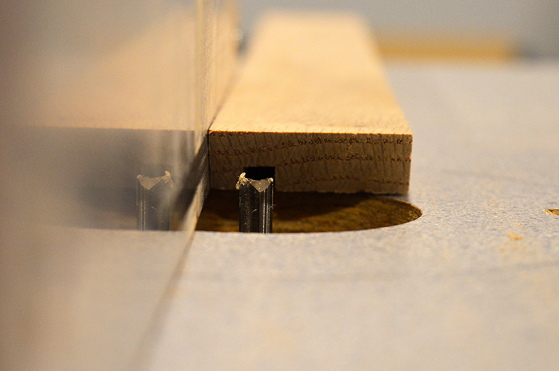
[EDIT] Since this post was published I realized I forgot an important detail about the face panel slot. The face panel sandwich is 0.248″ thick which does fit in a ¼” slot. Tightly. Because the design calls for the face panel to be removed and reinstalled easily in case changes are needed, the tight fit is a problem. The enclosure will be glued together with the exception of the bottom board which will be screwed in place. If change is required I can unscrew the bottom of the enclosure and slide out the panel face. The 0.002″ clearance is too tight for this to work well. My solution? Cut the groove, place two layers of masking tape on the router fence, and cut the groove again. Worked well. Panels now slide easily in the slot without noticeable slop. Sorry, forgot to take a picture of tape on fence router cuts.
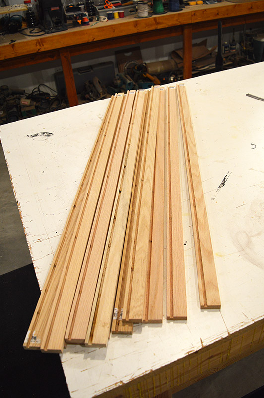
Then it was off to the compound miter saw to cut into finish sizes.
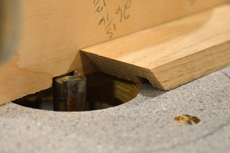
Back on the router table, relief cuts were made with a ¾” straight cut bit to accommodate the printed circuit board that will mount the wiring connectors. This is a stair step cut requiring two passes at different depths. Only the bottom and side panels require relief cuts.
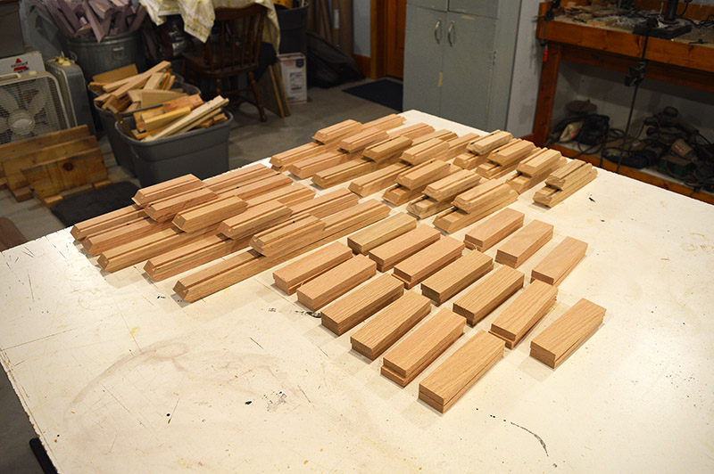
And then the monotonous part begins – hand sanding with 180 grit. The router cuts real clean but invariably there are little fibers left hanging here and there. Additionally, you have to break the mill finish on the oak otherwise it doesn’t take stain well. I did a few boards each evening. Doesn’t take much of this kind of work to make hands and fingers start cramping. It’s a hobby, right? No rush.

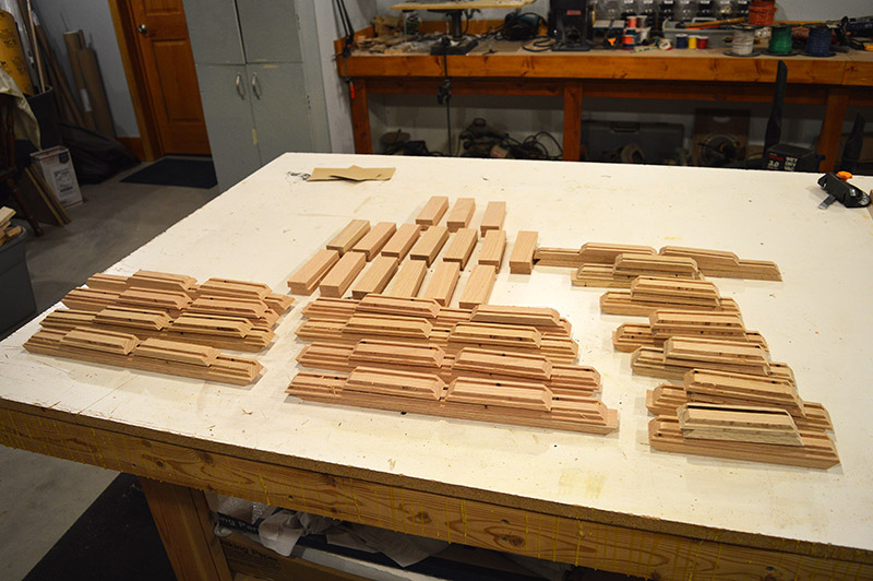
Eventually every piece was sanded.

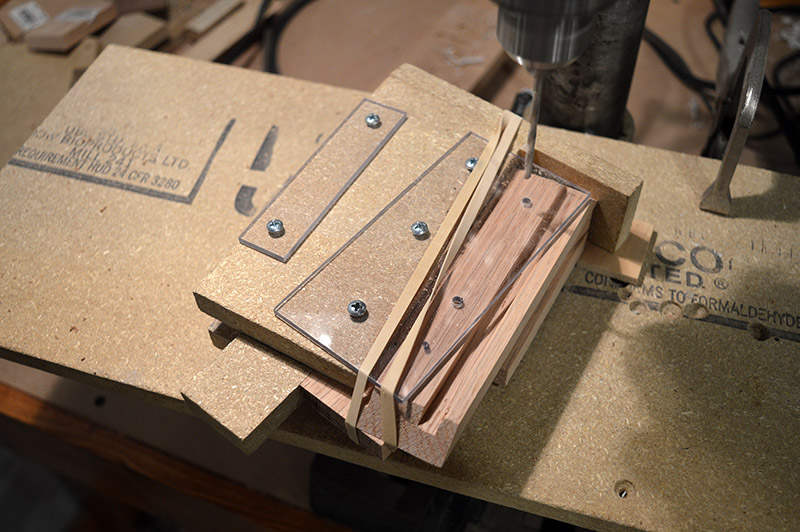
One last machining step to go – mounting holes for the side blocks. This step felt tricky to replicate uniformly so a jig was in order. A little bit of particle board, Lucite, and wood glue produced this:
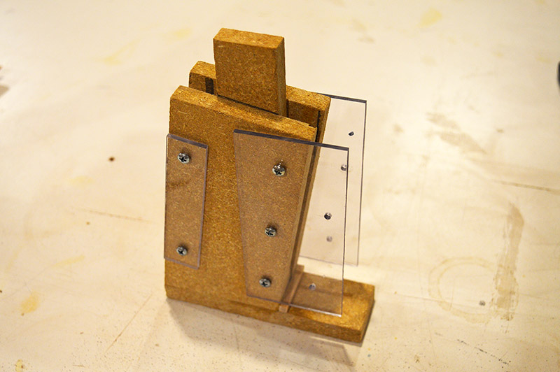
The side block and panel side fit in the jig at a perfect 10° angle ready for drilling.
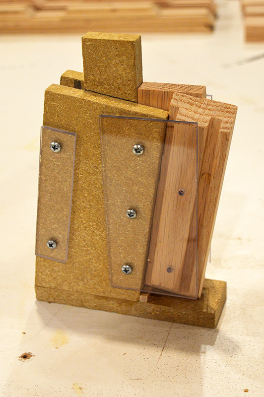
A couple taught rubber bands make sure the pieces don’t drift out of place during drilling.
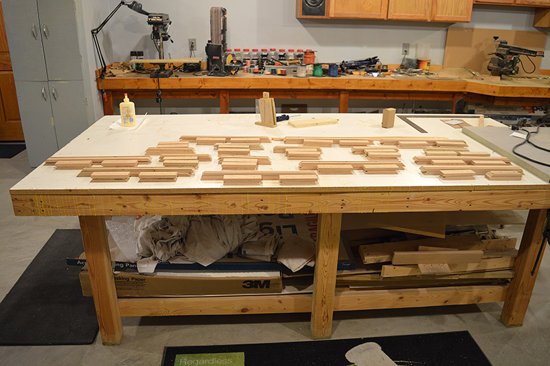
Presto! All the wood panel components are ready for stain and urethane.
I have begun the staining process. More on that in the next post.

Thanks for the update Alan! I like your jig, always neat solutions to your process.
it good to see your update your posts are going to help me with my new layout so if you post a update every week or every 6 week i always check every day to see if you have a new post and check your old posts out and i always check your youtube channel out to see if you have upload a new video of your awesome work and i would love to see some more how to videos of your work too
Billy, if you subscribe using the box at the top right of the page then a notice will be automatically sent to you whenever there is something new on the LK&O.
hi alan i do get email but i like to come back to check old posts i think this is some great work
Glad to hear you find value in this website. Thanks for the compliment.