If you have been following along with my control panel build posts then you know I thought I had the process all dialed in. I was wrong.
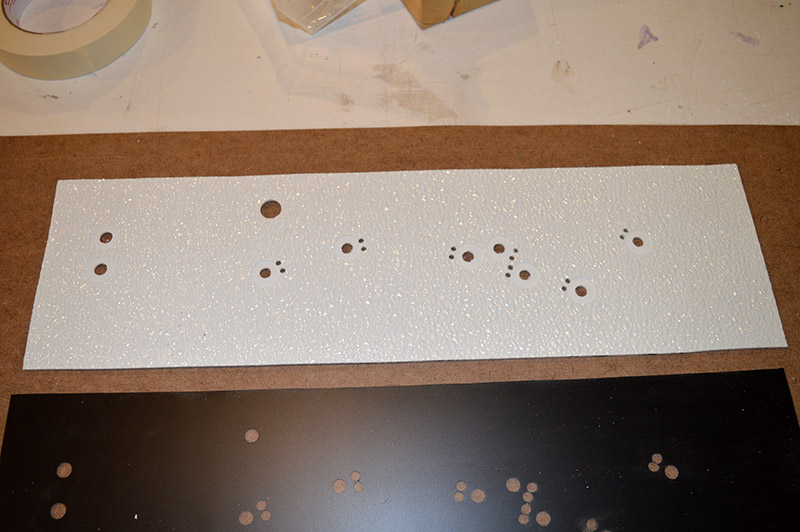
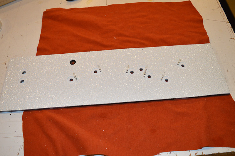
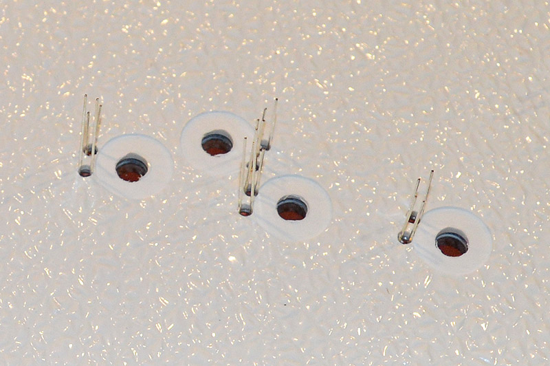
Everything worked as planned except the back panel that holds the LEDs in place. Soldering leads onto the LEDs before placing them in the panel face appeared to be a workable solution until I got to the second panel that had a lot more LEDs. Feeding wires through the back panel while keeping the LEDs fitted in the front panel was an exercise in frustration. I tried several alternatives – shorter wire leads, scotch taping the LEDs in place, and bigger back panel holes to name a few. Then I finally hit upon a method that worked – a single hole in the back panel for both LED leads and no pre-soldered on wire leads. More specifically, a single 1/8″ diameter hole. Big enough to easily fit the LED leads through but small enough so the LED itself cannot fall through thus retaining the LED in place. Hard to visualize from just my words I know. The pics below will better explain it. I generated a small pile of scrap during the experimentation but such is the cost of discovery.
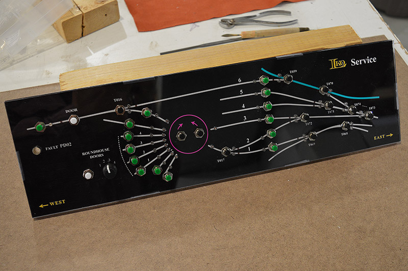
With process refined I have set about mass producing panels. I especially like the just finished Brittain Yard Service panel. So many knobs and buttons! Sorry about all the reflections. The panel faces are really glossy, almost mirror-like. Makes it difficult to take clean photos.
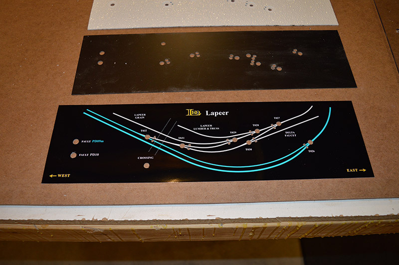
As promised in the last post, here is a step-by-step outline of my panel build process using one of the Lapeer panels to demonstrate:
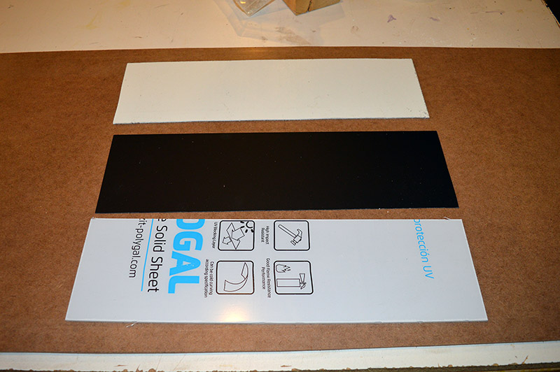
1. Raw materials
Face panel – 0.118″ polycarbonate, spacer – 0.030″ polystyrene, and back panel – 0.090″ FRP each sized 16¾” x 4¾”.
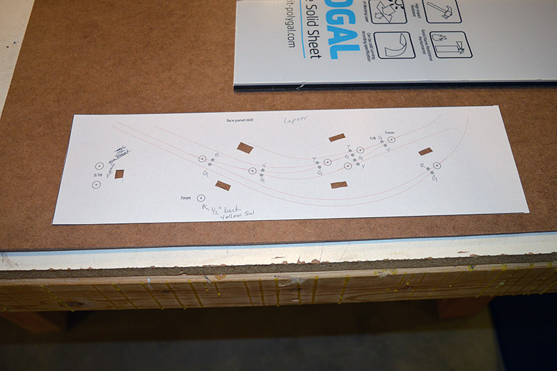
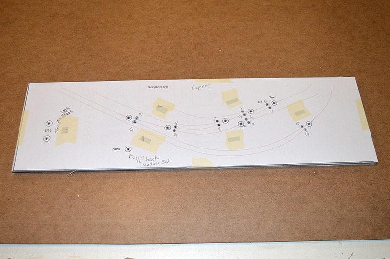
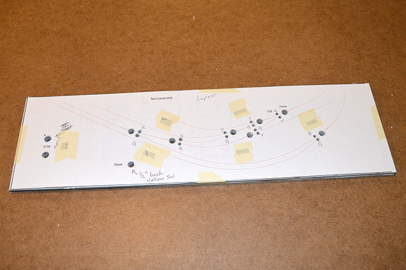
2. Drill template
Trimmed print of Illustrator design file showing only drill centers, hole outlines, and a thin trace of the track plan for reference. Printed on 11″ x 17″ paper. Slits cut for masking tape to keep the print from distorting when drill bit is withdrawn.
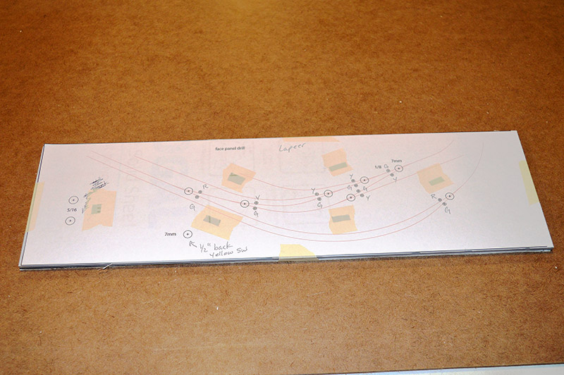
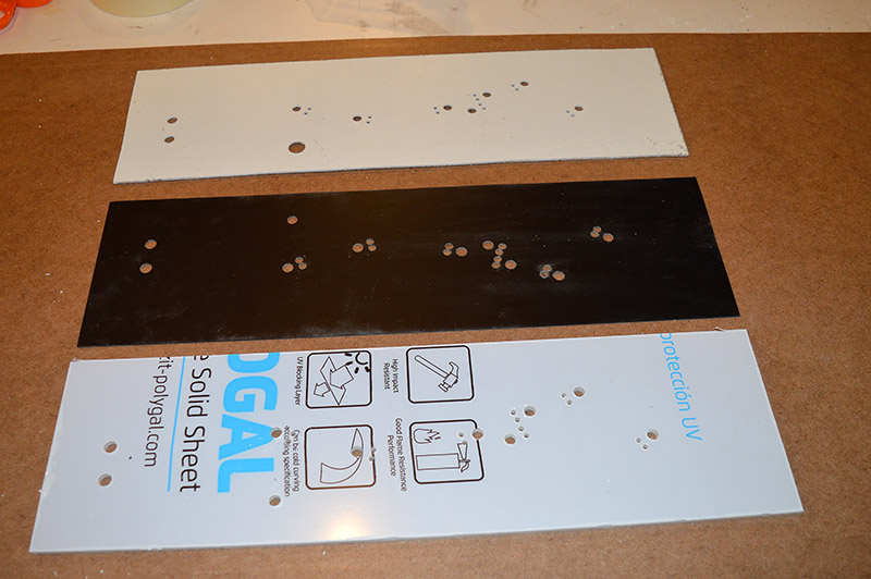
3. Stacked
The three panels and drill template stacked one atop another. FRP on the bottom, black styrene in the middle and clear polycarb on the top. Held together with masking tape.
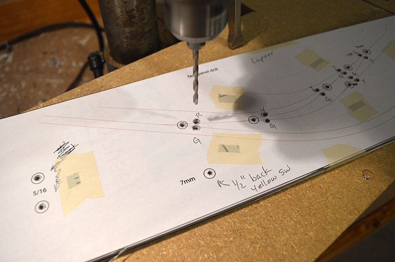
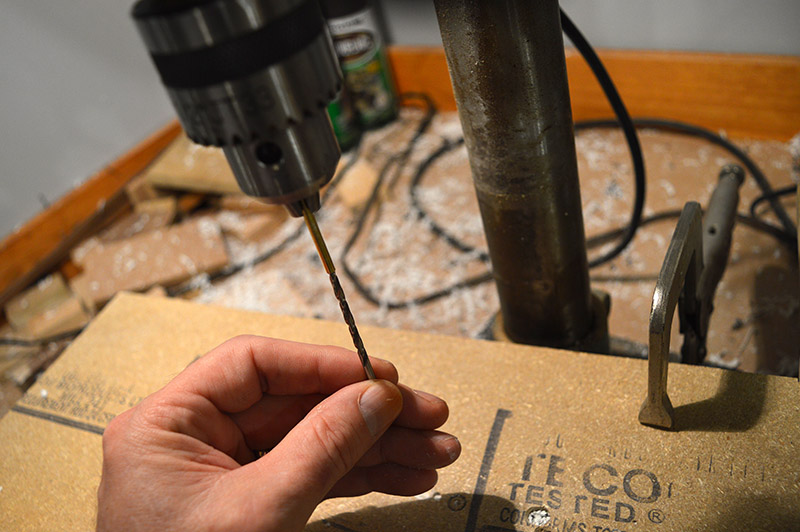
4. Pilot hole drills
3mm plastic bit with drill running at slowest speed.

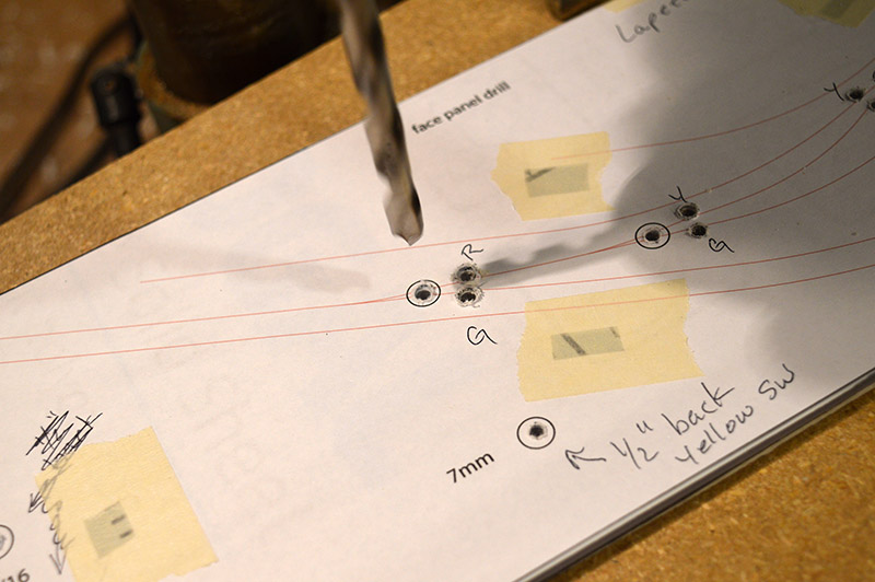
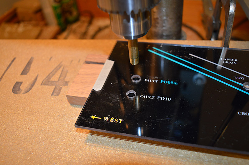
5. Finish size LED holes
1/8″ final size to fit 3mm LEDs
6. Finish size switch holes
7mm to fit push button threaded barrels.
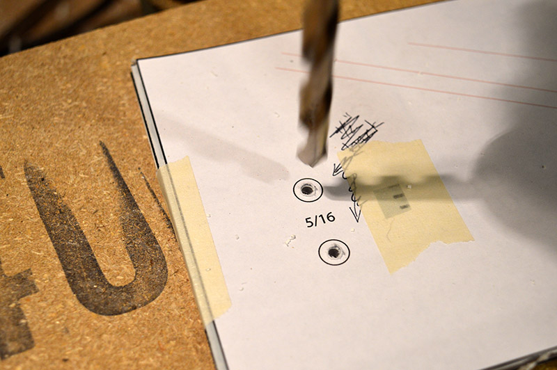
7. Finish size LED bezel holes
5/16″ to fit fault indicator LED bezel threaded barrels.
8. Drills complete, disassemble the stack
9. Switch body clearance drill
The threaded barrel of the black capped push button switches is sufficient to go through all three panels however, the green, yellow, and white capped switch barrels are not. This was remedied by opening the back panel hole to ½” so the switch body fits through for white, green, and yellow capped switches.

10. Spacer panel LED flange drill
5mm drill for ample clearance around 4mm LED flange.

11. Finished drills
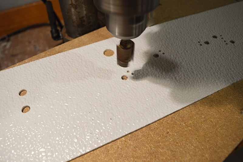
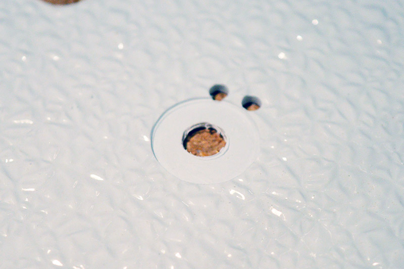
12. Back panel recess mill
The backside of the FRP bathroom panel is very heavily textured. Doesn’t make a good seat for switches and barrel nuts. A ¾” straight cut two flute router bit in the drill press becomes my poor man’s milling machine. Each switch and bezel hole received a recess cut.
13. De-bur drills
Plastics, in this case polycarbonate, styrene, and FRP, don’t ever seem to cut as cleanly as metal or even hardwood. A little TLC with a hand spun drill bit, a file, or even sometimes my fingernail was needed to clean up the holes.
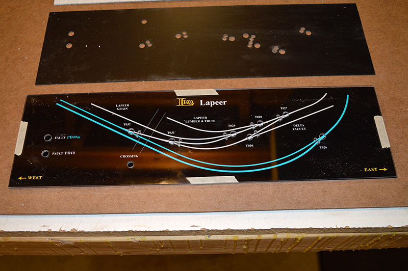
14. Place artwork
The inkjet print is trimmed and positioned underneath the clear front panel. Masking tape holds it in position.
15. Prepare paper drill
A tool steel paper drill would be ideal but I don’t have so brass tube has to suffice. Each size brass tube is sharpened by very lightly touching with a same size drill bit while tube is rotating in the drill press. Tube must be seated all the way into the chuck otherwise the brass tube deforms when sufficient chuck jaw tightening to avoid drift is applied.
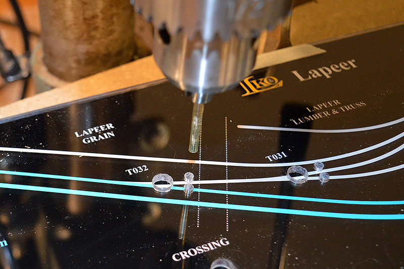
16. LED punch
1/8″ brass tube for the LED holes. You can feel it in the drill press feed when the tube pierces through the photo paper. Punching is done quickly to avoid heat buildup from the tube spinning in the polycarbonate hole.
17. Switch punch
Same process as with the LED holes except done with a 7mm brass tube for the switch holes. Shown with panel removed so you can see the marks in the hardwood board made by the tube.

18. LED bezel punch
Again. same process except 5/16″ for the fault LED bezels. Punching must be done quick with the larger size tube because heat builds quickly. Don’t want to melt the polycarbonate.
19. Punching cleanup
Just as with the drills, some of the paper punches need a little bit of cleanup after separating from the face panel. A new sharp Xacto knife does a fine job. Drilling plastic makes a tremendous amount of static clinging fragments. Each plastic panel and the photo print were vacuumed using the soft brush attachment.
20. Affixing the print in place
With all holes trimmed, the print, face panel, and spacer panel are aligned using the drills as a guide. Scotch tape is used to hold the assembly together in alignment. The scotch tape is so thin it doesn’t interfere with fitment into the wood enclosure router cut. The tape is positioned so that it will not be visible once the panel is in the enclosure.
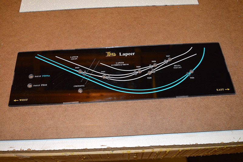
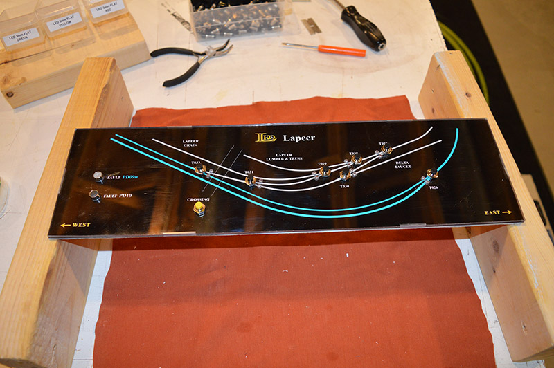
21. Installing LEDs
The “sandwich” is flipped over and LEDs inserted into their respective holes. A soft cloth working surface prevents marring the clear face panel.
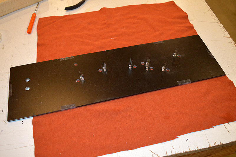
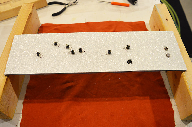
22. Fitting the back panel
This is the tricky part. The back panel is lowered into place by aligning the LED leads with their respective hole. It is a tedious process basically working one LED at a time across the panel. This Lapeer panel wasn’t so bad. The Brittain Yard Service panel shown at the beginning of this post was a real bear. It took me over an hour of gently prodding the leads to finally get the back panel to drop into place on the Service panel.
23. Fit the switches and bezels
The last step in the panel build process is fitting the push button switches and fault indicator LED bezels in place. They hold the whole assembly together.
View of the backside.
I have better than half of the panels built. Once I finish all of them I’ll make another post covering construction of the enclosures and finally wiring the panels.

Wishing all of you a very Merry Christmas and a prosperous New Year!

Excellent results, Alan. Your control panels will offer an outstanding touch to the layout. Merry Christmas and all the best to you and your family.
They look so good! Many thanks for providing the step by step process and sharing it with us.. Merry Christmas and all the best for the New Year.
Thanks guys. I hope you each find train goodies under your tree in the morning. I shook a box already. It sure feels to me like a new Alco RS-1! 🙂
Hi Alan:
I am new in the blog.
I working on panels the same way, but I use Universal Pre-drilled PCB, 3mm leds and 9mm Tact Switches (PCB True Hole devices). At this way you need a 4mm spacer between PCB and polycarbonate.
Of course need to draw the artwork on 0.10″x 0.10″ mesh.
If you want, I very glad send you pictures
Regards
Claudio,
Very glad to hear someone else is using same method. I have completed all of my panel faces and am extremely satisfied with the results. I hope you are having the same success.
I’ll contact you offline. If you wish to send pictures I will post them on this site.
🙂 I know you completed the panels!!!. I’ll send you pictures by mails, maybe it helps someone who start a same project.
Regads