Engineering work on the control panels continues as I await the arrival of components. Most of the stuff is here but a few items are still in transit. Meanwhile, I have modified the panel face design and solved two nagging problems – how to angle the panels and how to make the internal wiring interconnects.
Angled Panels
The thought of making the panel side frames as trapezoids and the edges of the top and bottom frames cut at a 10° bevel feels rife with problems for me. You have seen enough pictures of my shop to know I am not an accomplished woodworker. As Clint Eastwood once famously said “A man’s got to know his limitations.” Sounds like good advice to me. No trapezoid panels. I have come up with a much easier, and more doable, method of making tilted panels – side blocks! This not only solves the difficult cutting problem, it also greatly facilitates mounting to the layout. I’ll make the panels as conventional rectangles from ½ x 1-½” oak stock and then add vertical blocks on each side made from the same stock. Mount the panels at a 10° angle to the blocks. Mount the blocks to the layout. Presto! Nice angled panels made solely with right angle cuts. I think it may even look a little more stylish than plain rectangle panels. Here is a side view with everything drawn to scale:
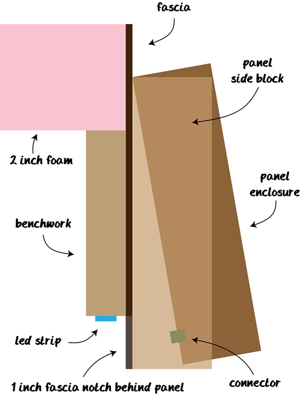
You may have noticed in the drawing the control panel is not the same height as the fascia even though I previously wrote the panels would be 6-½” tall, same as the fascia. I walked around the layout examining the land contour at each control panel location. There were several instances where the land dipped an inch or so below zero elevation at a panel location. Panels in these areas would have to be shorter otherwise they would extend either above the scenery or below the fascia. I don’t want that. I am also a fan of uniformity. I want all my panels to be the same height. 5-½” panel height will work in all locations so 5-½” it is. This actually occurred some time back. All of the artwork in the previous post is for 5-½” panels.
In the drawing above you see marked a notch in the fascia (dark gray). The bottom of the fascia will be cut away 1″ in height, flush with the bottom of the benchwork, behind the panel between the side blocks. This opening is where the wiring between track module and control panel will pass. The little green square is the electrical connector. This arrangement will allow for easy access from below while also avoid having wiring passing through holes in the benchwork. Wiring will not be visible because it is behind the control panel and above the fascia normal bottom edge.
Panel Face Arrangement
Recall this illustration from an earlier post:
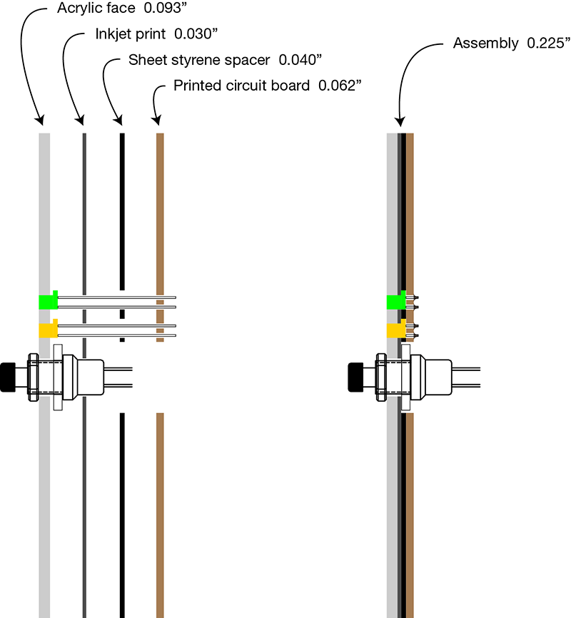
The design has evolved since the illustration was made. The clear face changed from acrylic to polycabonate and got a bit thicker, from 0.093″ to 0.118″. The inkjet print got thinner, from 0.030″ to 0.010″. To be honest, I don’t know where I came up with 0.030″ for photo paper. I measured a piece of Canon Photo Paper Plus Glossy II at 0.010″. The styrene sheet got a little thinner, from 0.040″ to 0.030″. This was due to accurate measurement of the LED base once they arrived. And finally, the circuit board on the back was replaced with a sheet of 0.090″ plastic. I discovered you cannot readily obtain positive resist pre-sensitized PCB in sufficient width for my panel faces (16-¾”). And even if you could, it would be seriously cost prohibitive. As luck would have it, I have leftover plastic sheeting from the installation of a back splash behind the wash tub in the basement. There was even a post about it on this blog back in 2010. This is the material at Home Depot. The description lists thickness as 1/16″ however when I measured it is actually 0.090″. The 1/16″ spec I suspect is a nominal measurement and is very close to the sheet thickness minus the cracked ice surface texture. The total overall thickness is closer to 0.090″ when measured at the peak of the texture. I am going to use it with the textured surface pointing inward so the smooth side will be against the styrene sheet. The new structure becomes:

The one change that has a material impact on the design is the elimination of the circuit board. Can’t solder LEDs to plastic! I have a solution for that too. Just as the switches will be connected, so will the LEDs with individual wires. From a mechanical wiring standpoint they will be treated no differently than the switches which brings me to the next subject…
Wiring Interconnects
Now that I know where the wires will enter the panel it was time to figure out how to connect them to the panel as well as configure the panel’s internal wiring all the while avoiding a rat’s nest mess of wires. Other than the switches and LEDs mounted to the face panel, there are a few more components required inside the panel – current limiting resistors and protection diodes. Originally, the resistors and diodes were to mount on the circuit board that forms the rearmost layer of the panel face “sandwich”. That is no longer an option. Instead, the resistors and diodes have to be included in the connector assembly. This turned out to be quite fortuitous. Allow me to explain.
I am using these connectors  in 10, 12, and 16 pin configurations. The pins are on 0.100″ (2.54mm) centers, same as a conventional IC chip. The plan is to solder these connectors to a circuit board which will then be mounted in an ¼” router recess on the back of the panel so the connector (green square) is positioned as shown in the illustration at the top of this page. As I began laying out a board diagram I realized the resistors and diodes would serve another purpose. They can be the jumpers that are necessary. That is the fortuitous part. The panels have to be made such that I can daisy chain them together because many Tortoises can be controlled from more than one panel. To accommodate this, and any future additions that also need daisy chain capability, I have resolved to making every connection in duplicate. In other words, every connector pin will be electrically duplicated in a mirror connector. When laid out on a board it looks like this:
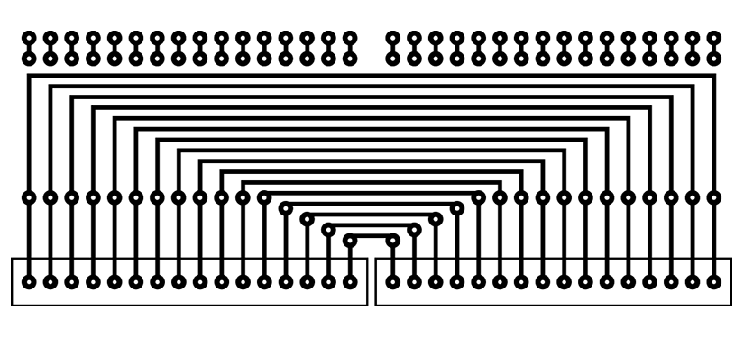
The connectors are at the bottom. The two center (vertically) rows of connects are for the diode and resistor connections. The top row of connects are for the wires to the switches and LEDs. As you can see, the resistors and diodes form the jumpers I would have needed anyway. Here is the same illustration with a few example components placed. By offsetting the components they fit nicely in 0.100″ spacing which is otherwise really tight.
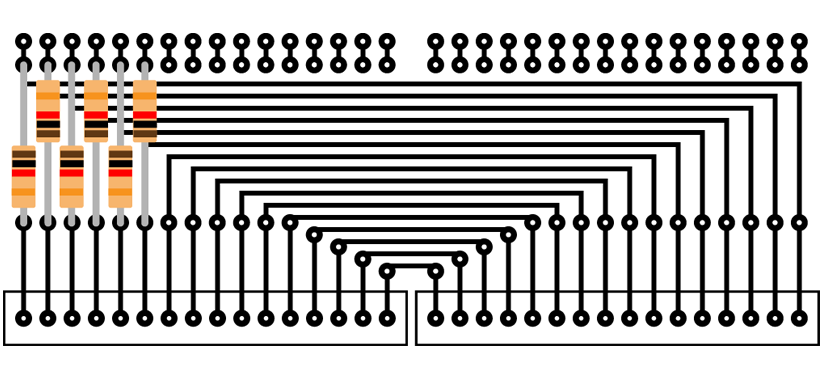
The blank boards I have on hand are 200mm x 300mm. From this size board I can get 6) double 16 pin PCBs. Two of these PCBs will fit well in a 16″ panel. That gives me 128 pins which is actually 64 pins because of the needed duplication. 64 electrical paths is more than enough for any of the panels. Here is what the panel will look like when viewed from the rear:
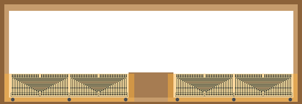
The wires coming from the switches and LEDs will fold over the top and solder into the PCBs hence why the boards are cut so close to the top row of connection points. The ½ width and/or panels with less controls will use a similar arrangement except with 10 or 12 pin connectors as needed.
Whew! That was a long winded post. I hope it gives you an idea of the details I am slowly plodding through. And people think building a model train layout is easy 😕

Very nice setup!! I have designed, and preparing to release a plug-n-play, signal system, that works like the real thing. The wevBsite is under construction, and is http://www.modelrailroadelectronics.com
This design makes installing and running a signal system, easy, simple, and actually fast to set up, and start using! If you have a layout, you can install the system, without ripping up any of your hard work!,
If you are interested, please feel free to contact me, and I can explain in more detail.
Bnsf_fan1@mail.com