If you happen to have been following my previous post about circuit breaker and block detector design, well no further need. This post presents the final design and working units.
I have included the necessary files for download if you wish to make your own. Links are at the bottom of the post.
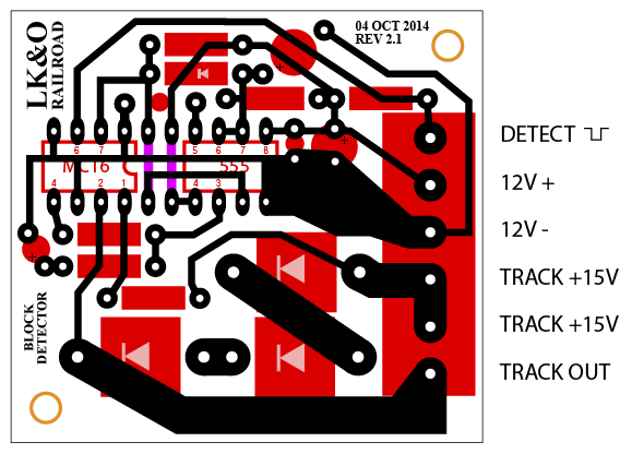
The circuit breaker design was good to go with the initial design. A slight adjustment of a few component values is all that was needed. The block detector was a completely different story. Even though the original author claimed the circuit can sense very small current on the track I was unable to replicate the results. The circuit required a locomotive under power for it to register block occupied. I wanted something much more sensitive. Something that would indicate occupied with only a single 15K ohm wheel set resistor on the tracks. The solution was to add a third diode in series to increase the voltage drop. You will see that addition reflected in the below pictures. The additional voltage drop was compensated by adjusting my track power supply higher. A setting of 16.9 volts yielded a track voltage of 14.8 volts after the detector.
The second issue I encountered was a very poorly shaped, slow rising and falling detect signal. I suppose I should have known this would be the case since the original circuit used only a transistor and RC network capacitor/resistor to control the detect signal. I wanted something with a clean, sharp on/off signal that I can feed directly to the signaling logic circuits (yet to be built). You notice I added a 555 timer chip as a one-shot with a full 1 second pulse width. The 555 is triggered by the optoisolator output transistor. The 555 switches from zero volts to almost 12 volts, the accessory bus power supply level. Once in the high state, the 555 stays high for 1 second then drops cleanly back to zero volts. The 1 second delay compensates for any rapid multiple triggers caused by train wheels momentarily losing electrical contact with the rails.
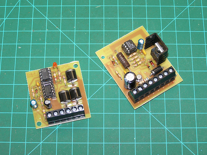
Both circuits have been fully tested and they work great. Confident the circuits are sound I set about mass producing them on PCB. Here is a picture of circuit breaker No. 1 and block detector No. 1 off the assembly line.
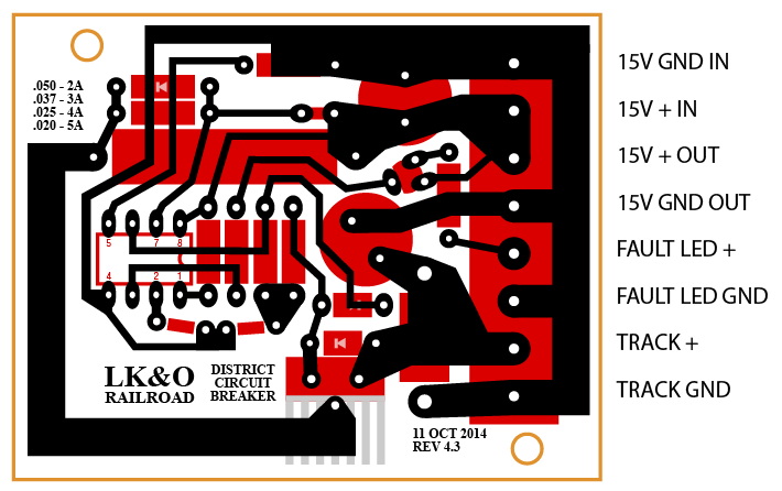
Here are images of the final PCB design.
And here are the files to build your own.
(both boards use Molex 38544 series connectors)
Circuit Breaker
PCB mask (Adobe Illustrator CS6)
PCB mask (EPS)
PCB mask (PDF)
Component list and board placement
Schematic
Block Detector
PCB mask (Adobe Illustrator CS6)
PCB mask (EPS)
PCB mask (PDF)
Component list and board placement
Schematic
Voltage Dropper
PCB mask (Adobe Illustrator CS6)
PCB mask (EPS)
PCB mask (PDF)
Component list and board placement
UPDATE
Breakers are done!
UPDATE
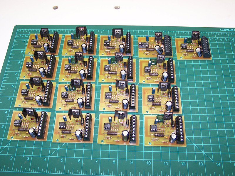
Occupancy detectors are done! All 32 of them.
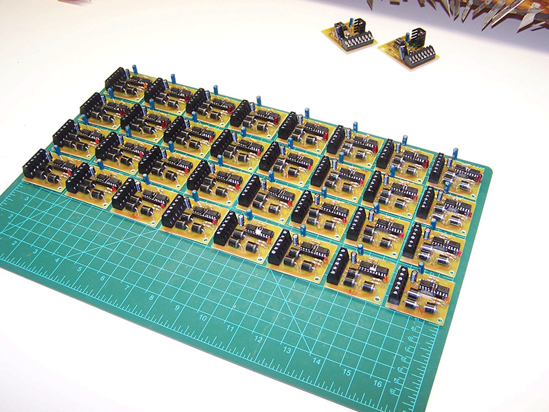
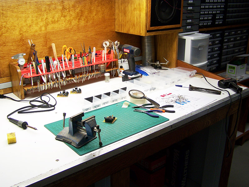
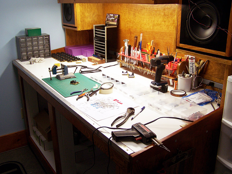
The workbench during circuits mass production. The plastic bins started out with a lot more components in them!
UPDATE
Added PCB mask and parts list for voltage dropper board (above). These are needed for sections of track that are not on an occupancy detector. It keeps the track voltage the same between detected and undetected track.
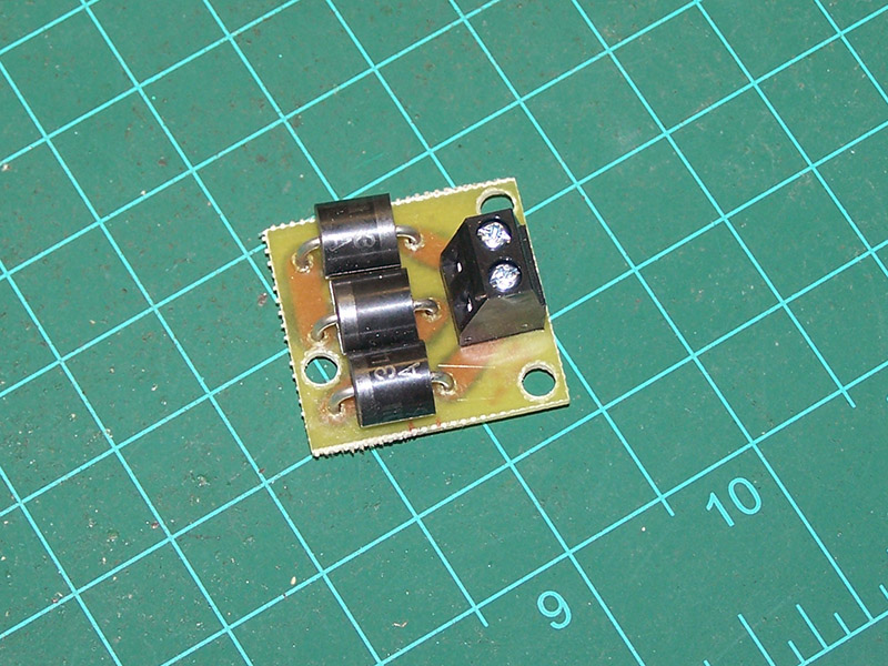

[…] occupancy detector circuits sense the voltage drop across diodes to indicate the presence of a train. For the track sections […]
Would you consider selling some occupancy detectors? I have trouble getting parts in Hawaii so gathering all the needed components and circuit board would take months.
Thanks.
Neil Erickson
55 Beckley Lane
Hilo, Hawaii 96720
808-960-0920
Sure, I could do that. Don’t really want to start a business around them but I wouldn’t mind making a few for fellow model railroaders.
I’ll contact you offline.
Alan,
would please post the voltage droppers mask and parts/placement. I understand you are busy, I am electronic illiterate but have followed your blog and am building tortoise controls. Thank you ,thank you.
Ask and ye shall receive. William, the voltage dropper materials have been added to this post.
Hi, do you have a video of this working & what are you connecting it to? i.e.. say an indicator LED to show loco in block
Ricky,
No, I do not have a video. There wouldn’t be anything to see other than an LED turning on and off. The outputs from the block detectors will be used for my signaling system. I have not built the signaling system yet. You could drive an external LED if desired. The output of the detector is a 12v logic level low with a train present and a 12V logic level high when no train is present. There is 30mA (max) drive current available from the MTC6 optoisolator. There is an LED indicator on the circuit board that uses 10mA of the available 30mA.
Any chance you can post the electrical schematic for your block occupancy detector final design? I noticed there have been several revisions since its initial posting and wondered where they are in the electrical circuit. I’m hoping to do something similar for block occupancy on my own model railroad, but have yet to find anything that is DC friendly without having to have a large load on the rails.
Nate, the schematic has been added to the file list above.
Thanks so much for that.
It is so nice to see a person share their ideas of circuits with other modelers who do not have a high knowledge of electronics, many thanks and well done
Hi Alan
Nice work above and like others had said, its great you are sharing you expertise.
Would this circuit breaker be applicable to a 24V garden railway where the Loco is quite a distance from the power supply and breaker? What modifications to the components would I need to make? Is the trip current variable?
Recently I found that a couple of my engines sustained damage after they had derailed, shorted and melted some of the plastic contact holders in the engine motor block. The 5A resettable circuit breaker on the Train Engineer ESC didnt trip at low speeds. I tested a 2A PTC Polyswitch, but at low speed (low V) it too didnt melt quickly enough to be feasible.
Rob,
The breaker would be applicable with a couple cautions: 1) The resistance in the circuit caused by the distance needs to be taken into account; 2) Adequate heat sinking on the MOSFET.
The trip point is settable by changing the value of R3. You would also need to change D1 to a 24V unit.
Note this design is only for DC. It will not work with DCC.