Some time back I posted about using homemade circuit breakers for power management on the railroad. The original post is here. Time has come I need to finalize how power on the rails is managed since it has a direct impact on wiring during track laying. Another aspect of the track wiring is block detection for signals. This too needs to be considered during track laying. Usually circuit breakers and occupancy detectors are two separate items. I have decided to incorporate the two together into a single circuit breaker/occupancy detector module. For short, let’s call it a CBOD.
This post will be updated as I move along assembling and testing the prototype circuit.
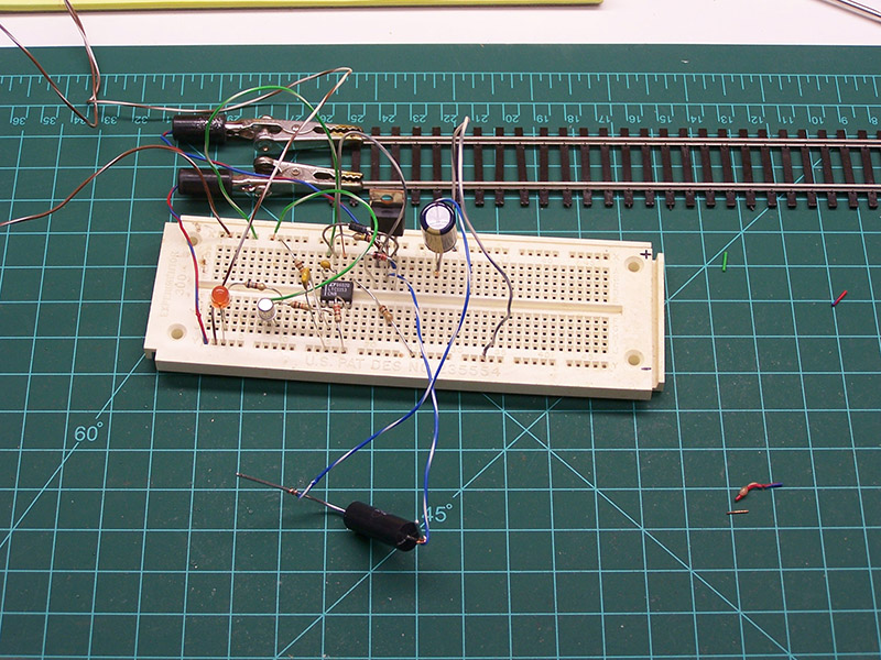
I did a quick breadboard of the LT1153 circuit breaker. Not that I had any doubt a circuit taken directly from the datasheet would work but I had to see for myself. Sure enough it worked as advertised. The breadboard has since been cleaned off to make way for the CBOD prototype.
An interesting side note…..
The same LT1153 chip I am using in my circuit breaker is also being used in an experiment on the International Space Station. Scroll 2/3 way down this page to the Daughter Board Hardware section. Cool! I’m using space stuff on my railroad.
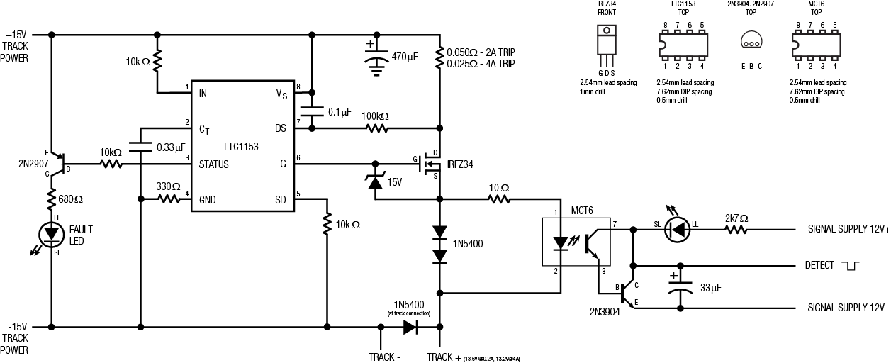
Below is the schematic I have settled on. On the left is the LT1153 data sheet circuit with a few modifications. 10kΩ resistors have been added to the IN (input) and SD (shut down) pins to safeguard the chip’s internal protection diodes. A 330Ω resistor was added on the GND (ground) pin to protect the chip from reverse polarity transients that may occur in the track power supply. Both of these additions are spelled out in the data sheet. The STATUS pin is normally used to interface with power management controllers. It goes low when the breaker flips. In my circuit the pin is driving a transistor to light a fault indicating LED that will be located on the respective fascia control panel. The only other change from the data sheet circuit is the zener diode voltage. My track power is 15v, not 12v, so the change was needed.
On the right is the occupancy detector circuit. I take no credit for designing it. It is straight from the Circuits4Tracks web site. The design is so simple and elegant. Track power is fed through a pair of diodes each dropping the voltage 0.7V. The total voltage drop across both is 1.4V. An optoisolator is connected across the diodes so that it sees the combined voltage drop which lights the LED inside the optoisolator. Anytime current is flowing the optoisolator is triggered. The resistor in series limits the current to the optoisolator LED. Connected to the optoisolator is a transistor that amplifies the optoisolator output. Even if the optoisolator LED barely glows the transistor will conduct pulling the detect line low. The capacitor delays the turn off time to prevent chattering from dirty wheels or other intermittent wheel/rail problems. An LED is present for use as a troubleshooting indicator. It too will light when the transistor is conducting.
Stay tuned as either I get a functioning CBOD or release the factory sealed IC smoke!
Click the schematic image for a big readable version.
UPDATE 1
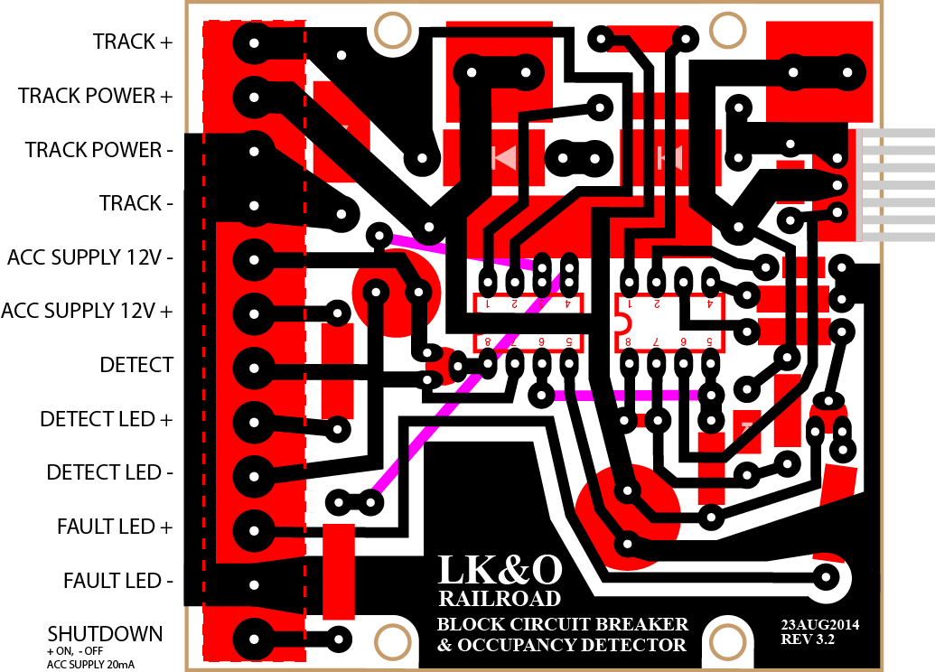
While I await the arrival of a few more electronic parts from Mouser I created the PCB art. This way I will be ready to make boards assuming testing continues to go well. Even if testing shows I need to make some changes at least I am ahead of the game. Besides, it’s fun!

UPDATE 2
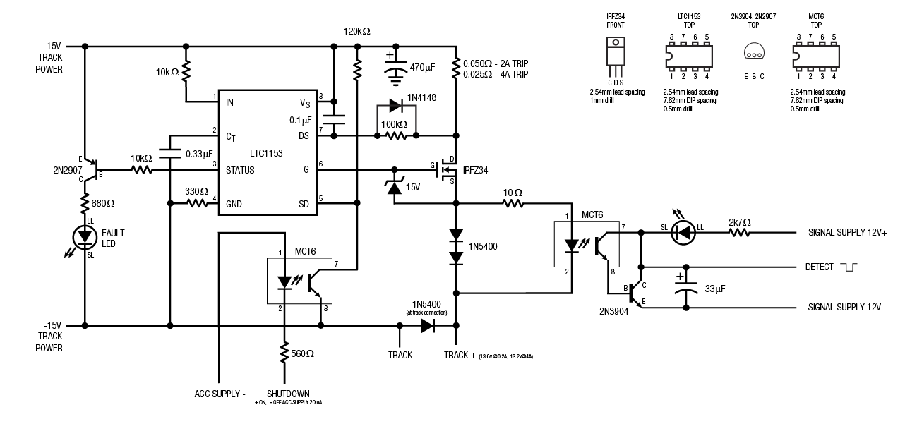
Added logic control to the circuit breaker. This will allow remote shutdown of the block by another device such as a sensor. Rather than rearrange the entire circuit board I opted to use a few jumpers (magenta lines). The MCT6 optoisolator is a dual package only one half of which was needed in the original design. I used the remaining half to control the shutdown pin on the LTC1153.
UPDATE 3
Testing revealed the need for a soft start circuit. If several sound equipped locomotives are on the track during power up then it is possible to momentarily exceed the trip point of the breaker. This is because of capacitors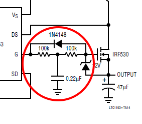 in sound modules presenting essentially a short circuit until they charge. They charge fast but not as fast as the breaker trips.
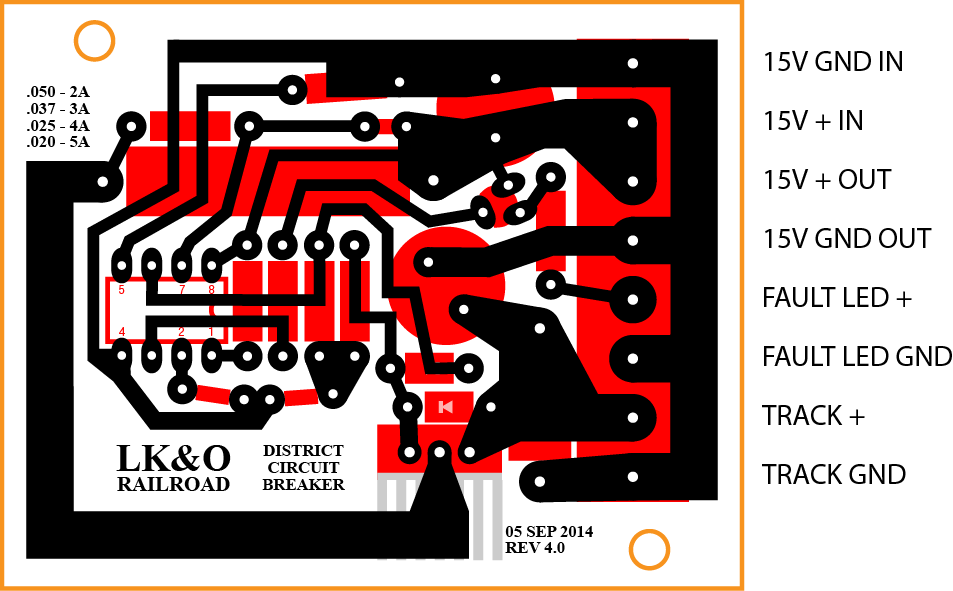
Fortunately, the data sheet had just such a circuit modification. The soft start addition is two resistors, a capacitor, and a diode connected between pin 6 and the gate of the MOSFET. The resistors and capacitor form a RC network which slowly raises the gate voltage during power up thus limiting the initial current flow in the transistor. The diode bypasses the RC network for quickly discharging the MOSFET gate when the breaker trips. Made the change to the prototype and it worked great. The addition is reflected in the art below.
After scrutinizing the location of the power districts on the layout and comparing to the location of the detection blocks it became apparent that it would be wasteful to use a CBOD in every location. It makes much more sense to use separate circuit breaker and detector boards in certain areas. I am still working out the exact boundaries of each block and power district so I don’t have a diagram for you just yet. I’ll post one as soon as I settle in on a final arrangement. After coming to this realization I set about creating the mask art for a circuit breaker only board. Here it is:
UPDATE 4
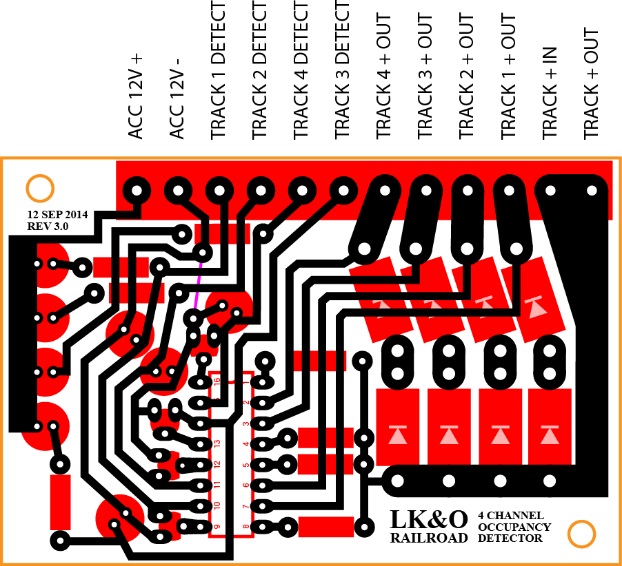
With the circuit breaker artwork complete I moved on to creating the artwork for the occupancy detector PCB. I found that buying a single quad optoisolator is much more economical than two dual units. So I designed the circuit to make use of an Infineon ILQ74 chip, a quad emitter/detector pair unit. There is nothing unique about this particular chip. I was placing an order for other items and this Infineon chip just happened to be one Allied Electronics had on the shelf. It has the same electrical specifications as the MCT6 chip in the above schematics. A drop in replacement.
Below is the art for the board. Finished size is 2″ x 3″ mostly because of all the space the big hunkin’ 1N5400 diodes take up.
I am all set to etch boards this weekend for both the circuit breakers and the occupancy detectors. Wish me luck!
UPDATE FINAL
I have made numerous changes to the circuits to get them to work as I want. Rather than bury the final product deep in this post I decided to create a new post. For the final products see this post.

[…] you happen to have been following my previous post about circuit breaker and block detector design, well no further need. This post presents the final […]