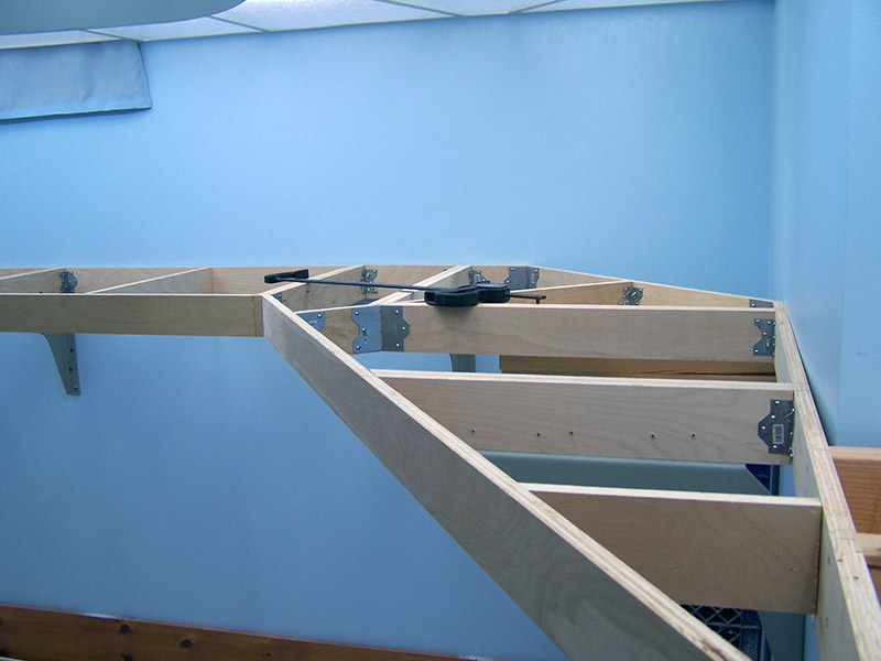
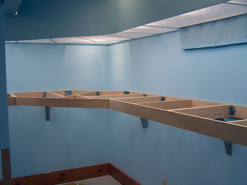
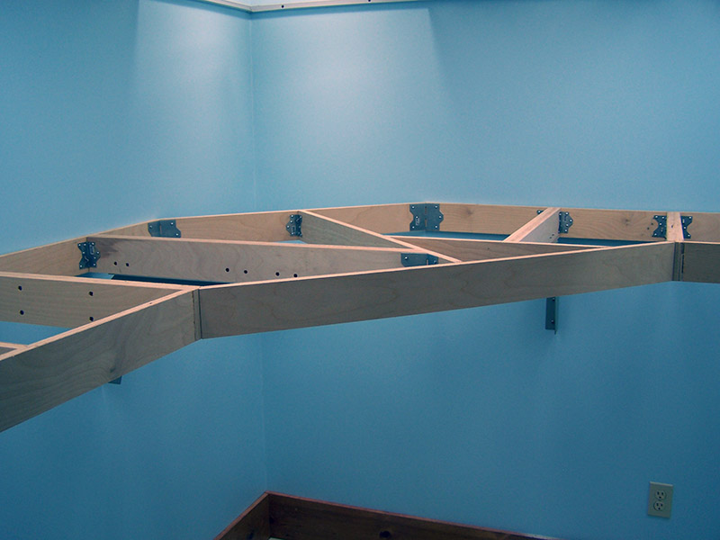
I have made considerable progress on the benchwork over the past two weeks. The benchwork along the three walls of the basement are in place. So brings an end to the easy to build, 2 foot wide, 90 and 45 degree angle benchwork! As I start along the backdrop wall the angles and benchwork shapes are all odd shaped. This means a lot more measuring, check fitting, and changing the saw angle. Thank goodness for protractors and straightedges. 🙂
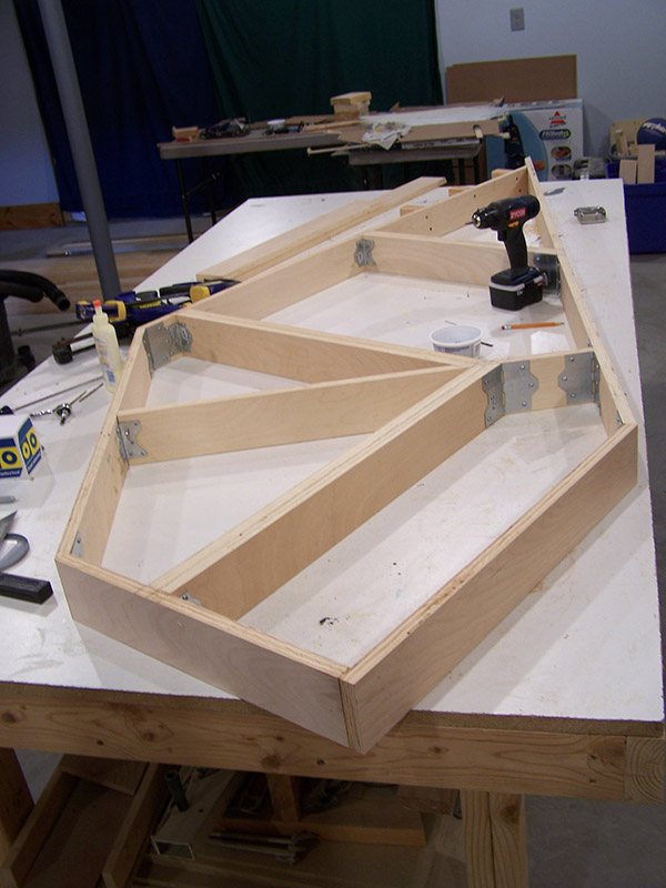
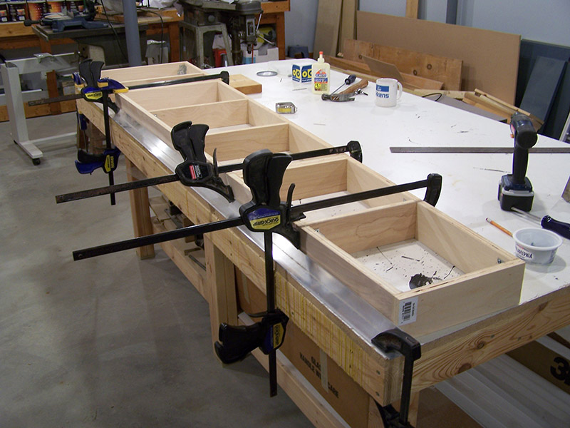
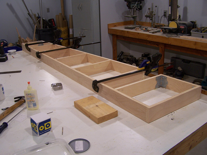
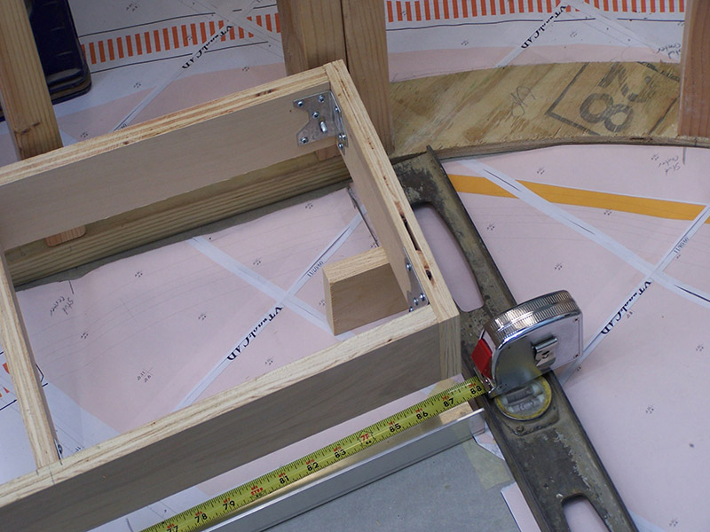
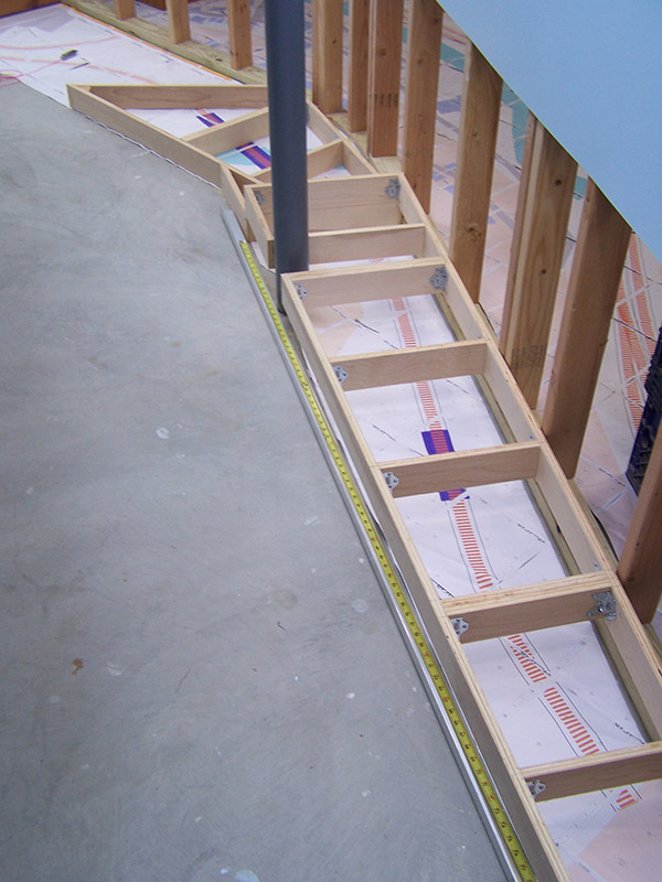
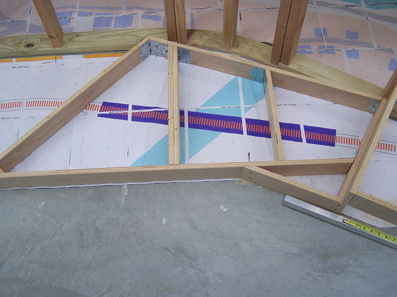
The printed track plan on the floor is my guide. From it I measure lengths and angles. Those measurements are then used to build the outer perimeter of the benchwork section in the workshop. Once the basic outline is completed the section is placed on the floor on the track plan print. If all lines up well then cross member locations are marked. In the spirit of full disclosure I must admit not each time has the perimeter layout been correct on the first try. An itsy bitsy angle measurement error can expand to a big error at the other end of an 8′ board. Sometimes disassemble and a little trimming is needed.
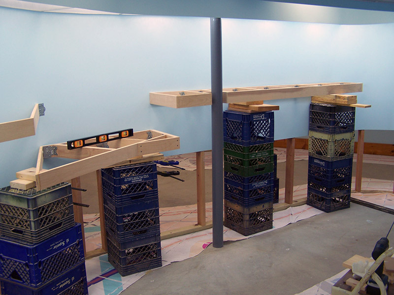
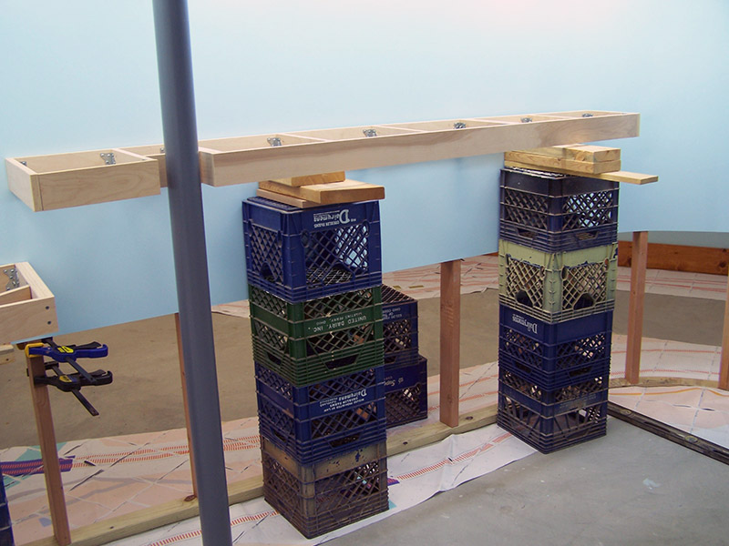
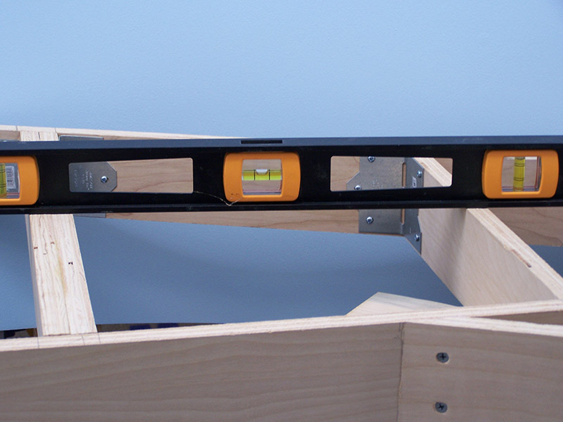
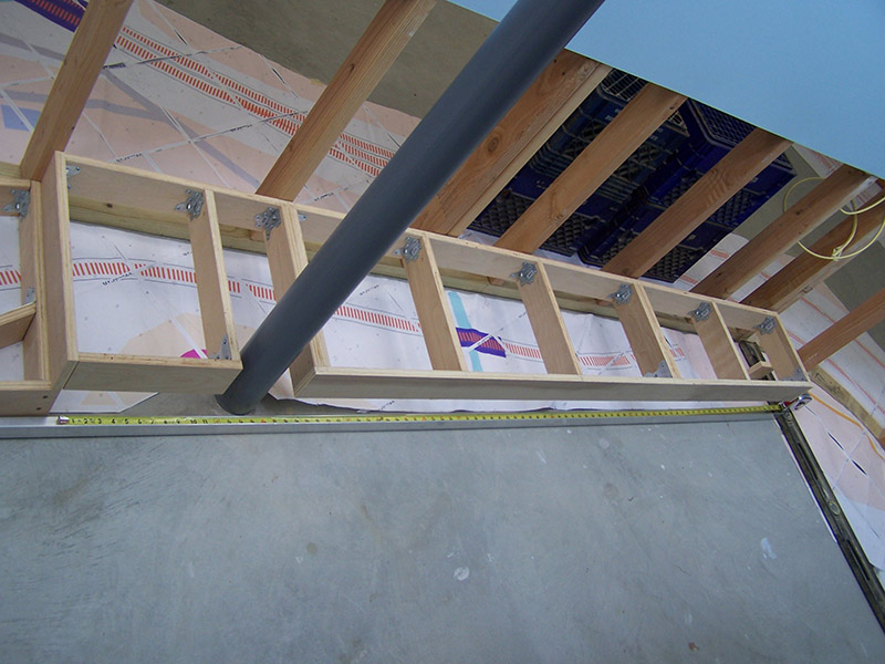
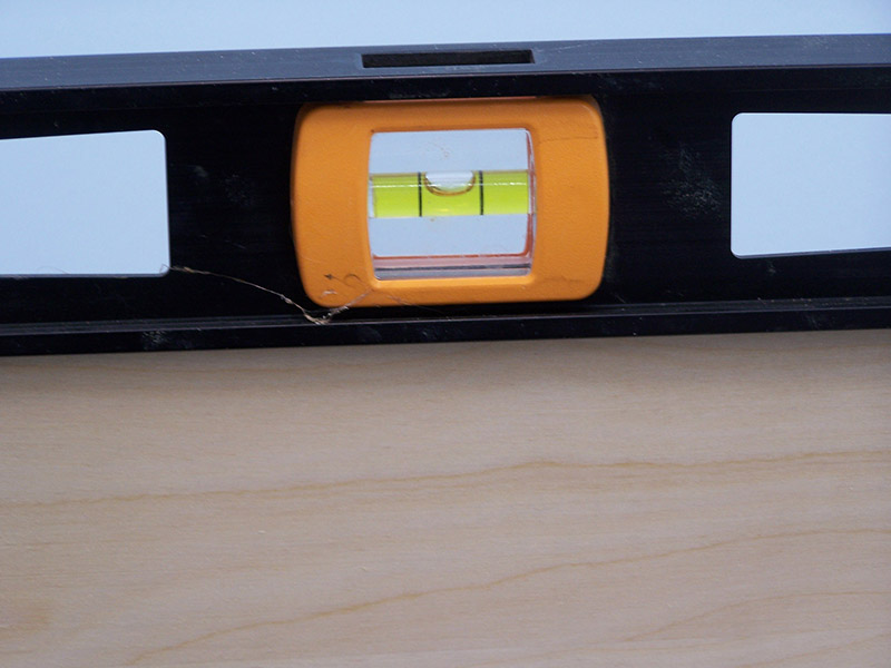
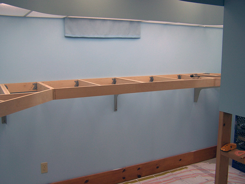
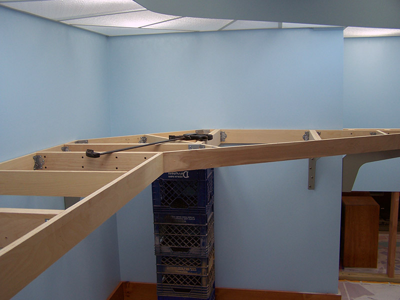
After the cross members are installed the section is placed on milk crates and shimmed to set it at the right height. The final zero elevation is to be 53″. So with 2″ scenery foam and 3-1/2″ tall benchwork, the bottom of the benchwork is 47-1/2″ from the floor. A plumb bob is used to align the section with the track plan on the floor. Once in correct alignment, additional shims are placed as needed to make the benchwork section level in both x and y axis. It gets to be a little bit of back and forth action trying to get everything level all the while staying as close as possible to 47-1/2″ height at all positions. The concrete flatwork in the basement must have been done by a pretty darn good mason because the height measurements have not been off by more than 3/16″ when everything is level. That’s some level and flat concrete work!
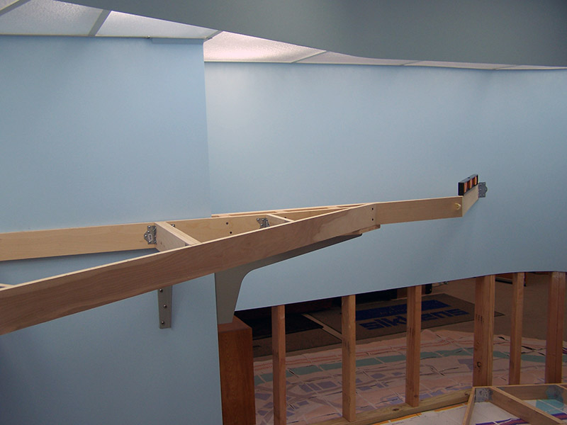
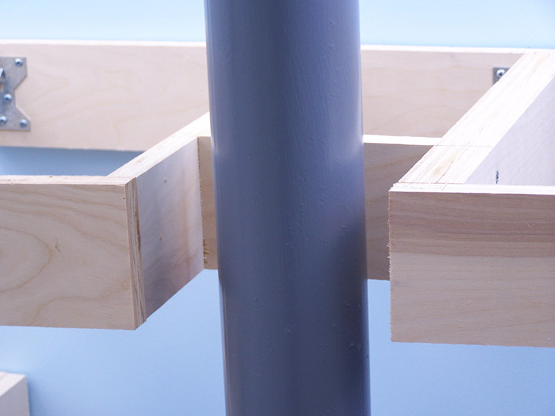
Here are a bunch of pics from my progress since last post. The irregular angle benchwork begins as I approach the backdrop wall, an area that will eventually become the bridge over the River Styx. Of course, my railroad is in 1969, long before the housing developments were there. This is also the spot where I have to work around that pesky post in the train room. Thankfully, there is only one.


First time I have been to your site. I linked here from MRH. This is my first time to the site and I love the benchwork and the brackets. If I could make on comment from my experence with my club’s layout. You may already being planning this, (looks like a lot of planning has gone into this) but I recommend you put wire holes thru all of your cross members. I would come up with a set pattern of holes for every cross member to run your bus line, switch machines, your signaling, etc. We are currently drilling those holes from underneath the layout and it is a pain.
Arthur,
Thanks for visiting the site. Hope you continue to follow along as my adventure continues.
Your suggestion of drilling wiring holes at this stage of construction would normally be an excellent idea. However, in my case there is a very deliberate reason for waiting. I want to position all of the sub-roadbed risers and Tortoise machines prior to determining wiring raceway locations. The layout will be wired (except track feeders of course) before the sub-roadbed is permanently placed so I will have wiring access from both above and below. The cross member holes will be drilled with a right angle drill so after-the-fact working clearance is a non-issue. I am right with you about wiring from below. No one likes working upside down especially considering the amount of soldering that will be needed. Ouch! Hot blobs of molten solder falling on me is not part of the plan.
Stay tuned to the blog. When I get to the wiring stage there will be photos (I love photos) that will make everything much clearer why I am taking the approach I am.
Alan,
Well, I will have to go back to my statement “you may already be planning this…” I have to say you are setting the bar on how to design, plan and build. In the past few days I have been doing nothing but reading through your posts. I plan to use this as examples for our club layout. Thanks for the great job.