The very first piece of benchwork is built. Section #1 of the upper deck. Not much but hey, you have to start somewhere!
One of the top benchwork design criteria is to keep the deck thickness to a minimum. Every additional inch of deck thickness is one less inch of space above the lower deck. Contained within the benchwork 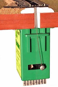 will be switch actuating machines called Tortoises. These nifty little gear motors move the throwbar of a railroad switch from side to side to change the line up or route of the tracks. Tortoises are rectangular devices about 2″ x 2″ x 3-1/4″ in size. The benchwork has to be designed so as not to interfere with the positioning of the Tortoises directly below the throwbar of switches. Hence the paper track plan is back in position on the floor to show me exactly where the throwbar and associated Tortoise of each switch is located.
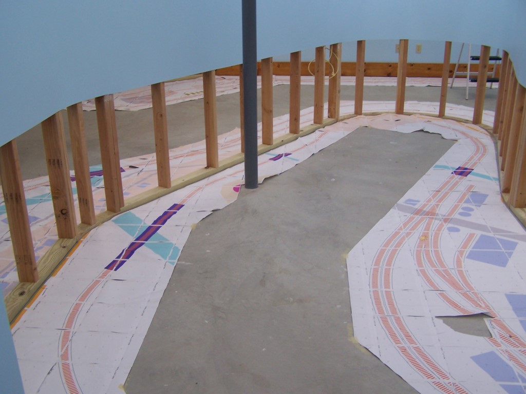
Another consideration is the the location of the wall studs where the support brackets will be attached. A cross member must be located every 3-4 feet along the benchwork and aligned with a wall stud so that a support bracket can be affixed. Not much room for error since the wall studs are only 1-1/2″ thick and the screw cannot be too close to the edge of the stud. Locating the bracket cross members really needs to be spot on. Additionally, the center-to-center of the cross members must be held to roughly 16″ or so to provide adequate support for the sub-roadbed that will eventually be on top. Too great a distance between cross members could result in sag of the sub-roadbed and that would be a very bad thing.
So there you have the measurement considerations taken into account as I build each benchwork section – 1) where are the wall studs; 2) where are the Tortoises; 3) how far apart are the cross members.
My construction method is a bit of a departure from the norm. I am using framing angles at the board joints instead of simply screwing into the end grain or using pocket screws. Screwing into the end grain is never a great method but is even worse with plywood. Not really usable at all. Plus the screws on the wall side would be inaccessible once the benchwork is in place. I want the option of relocating cross members from below. If a track change occurs in the future or I need to add an actuating motor for something like a railroad crossing gate then I don’t want cross members to be permanently in place. With my luck a cross member will be right where I need to mount something! If I need to move one then I want to be able to do it without disassembling anything but the cross member itself. Pocket screws would be the next most logical choice however I found them also to be less than ideal in plywood. I tried pocket screws on a couple test joints made from plywood scraps. The screws had a tendency to separate the plies of the plywood when I tightened them. It didn’t happen on every joint but it did happen on a few. Even a few would be too many for my taste on the actual benchwork. So, framing angles became the selected method. Normally used with nails in the construction of a house, framing angles are strong, inexpensive, and work great with taping screws in place of nails.
Framing angles come in a wide variety of sizes, shapes, and configurations. I selected Simpson StrongTie #A34 because it is a simple right angle sized appropriate for a 3-1/2″ stud.  Or in my case, a 3-1/2″ board of 3/4″ plywood. For angles other than 90 degrees I used Simpson StrongTie #LS30 skewable. The framing angles are attached with #6 x 1/2″ sheet metal screws. Using framing angles as connectors is not a speedy construction method. Each joint must be clamped, screw holes located, pilot holes drilled, and angles attached. Since the framing angles do not draw a joint closed like a conventional fastener, the joint must be tight and square before the angle is placed. This means a lot of clamping to the workbench and across the benchwork section to hold the cross member tightly in position during fitment of the angle. A bit slow going but the end result meets the criteria and produces a very strong, rigid section of benchwork.
The regular cross members are a single board attached with a single framing angle on each end. The framing angles are on opposite sides of the cross member from end to end. The cross members where wall brackets are located are doubled up to create a surface 1-1/2″ wide the same width as the wall stud and the bracket mounting face.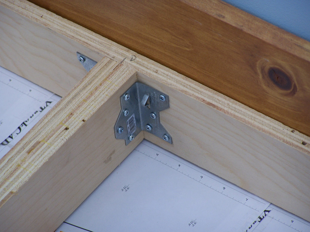 The doubled cross members are glued face to face, clamped, and left to dry a day before being installed. 1-5/8″ drywall screws are driven through the doubled cross members in a 4×4 pattern so as to box in the area where the #14 screw coming up from the bracket will penetrate the cross member. Since this is technically end grain fastening I took the gluing and box screwing action to prevent ply separation and to make the connection pull out resistant. A quick test joint indicated this method to be very strong. Using the hydraulic operated loader bucket of the tractor I leveraged a test piece until it failed. The plywood split elsewhere before the boxed in screw let go. Good enough for me.
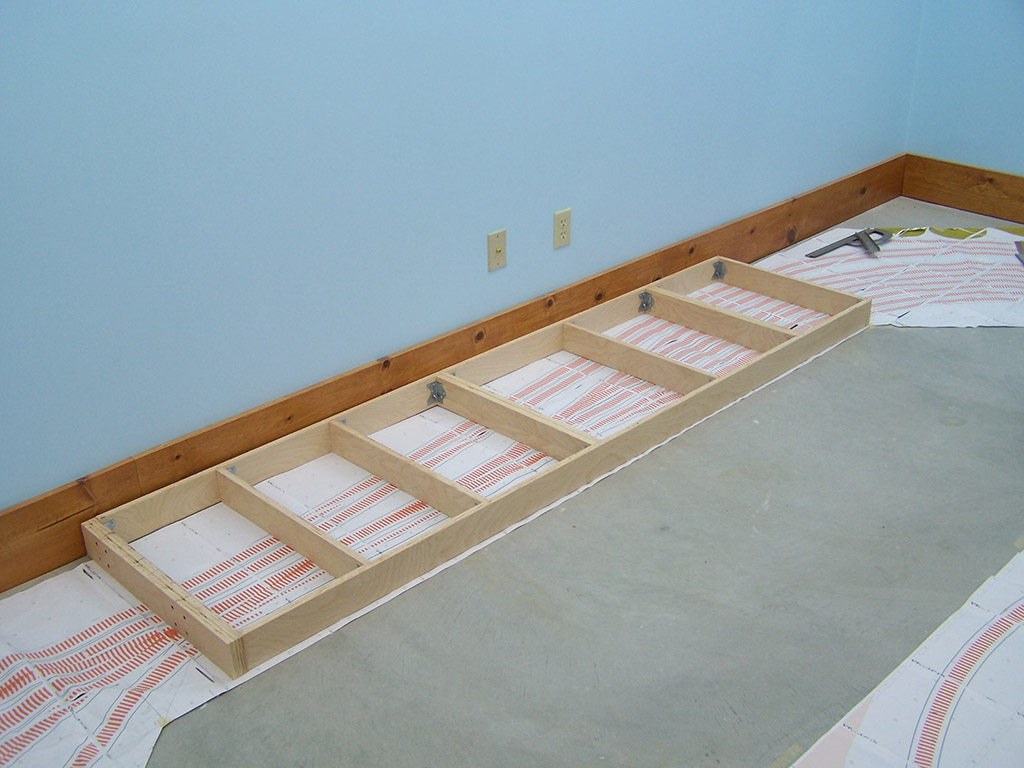
Section #1 is the west end throat of Brittain yard. I started here because this area has the highest concentration of switches. If I can get cross members in the right places in this section then everywhere else will be easy. So far, so good!

Why the double piece in the middle? Is that for added structural integrity?
The double cross members are where the shelf brackets mount. The brackets have a 1-1/2″ flange on them. Giving myself 1-1/2″ of wood mounting surface means the brackets don’t have to be in perfect alignment to still allow the screws to grab good wood. Am using #14 screws. That’s a hefty screw. If the cross member were only 3/4″ wide (single board) then the bracket alignment would be super critical. I did it this way to give myself a little leeway.