Summer sure does slow down progress on the train room. Practically to a standstill. Who wants to be in a basement when it is a beautiful day outside? Still, minor progress has been made.
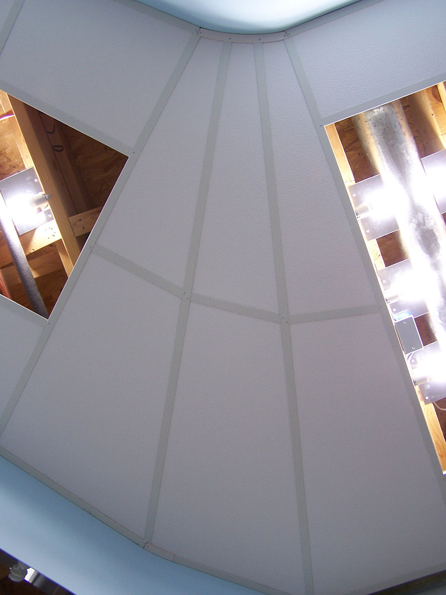
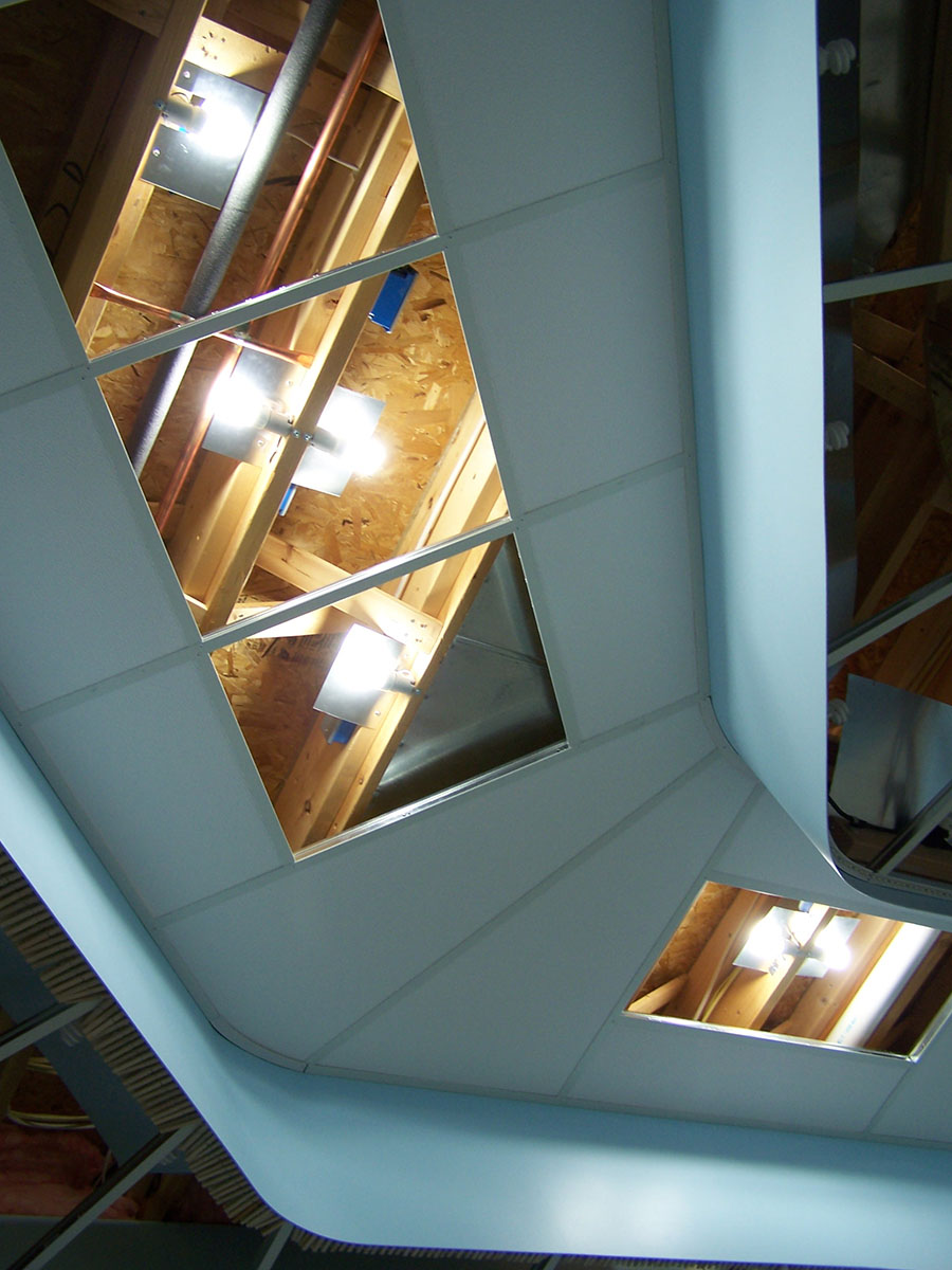
I have a working solution for determining the shape of the ceiling panels. Due to the arrangement of the grid there is not a single standard size 2’x4′ rectangular panel in the room. Each and every panel is different in size and shape. I needed a means of creating a template for each opening.
Yardsticks, hardboard scraps from building the valance, coat hanger wire, and wing nuts put me in the duplicating business. 
 A quick router cut to make the yardsticks into sliders, cutting and bending of the coat hanger wire to produce the proper inset distance of the panels into the rails, holes drilled in the corners of various size and shape hardboard scraps, and masking tape angle indicators is all there is to it.
To use the tool I hold it up to the ceiling grid and slide the yardsticks into approximate position. Next, the wires are twisted so they point into the corners of the grid. The yardsticks are then loosened slightly, moved to place the wire in the corner of the grid exactly, and re-tightened. Any needed fine adjustment of the wire angles are made and the wing nuts tightened securely. It sometimes takes multiple adjustments to get everything right but is a tolerable operation.
Once the wires are in their correct positions the tool simply hangs from the grid. At this point masking tape with an ink marker line on it is temporarily stuck on the end of each yardstick so as to indicate the angle of the wire hooks relative to the yardsticks. Two wires on the same end are swiveled to release their wires from the grid and the tool taken down. Repositioning the two swiveled wires back to align with the masking tape marks returns them to the proper angle.
The tool is laid on a new panel on the workbench and ink marker marks are made under the point of each wire. A straightedge held down with light pressure from dot to dot allows me to accurately cut the panels with a razor blade knife. Two passes are required. One light first pass just enough to cut the plastic facing on the panel, the second pass to cut the fiberglass insulation. Trying to cut all the way through in a single pass doesn’t work well. The plastic facing occasionally rips away from the fiberglass with a single cut.
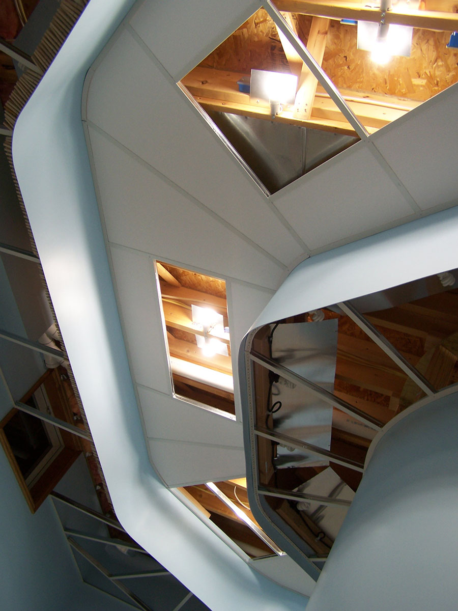
Although it may sound risky, I simply freehand the cut on panels that have a curved side. The straight sides are cut first and then the curve cut is by eye after referencing the curved grid angle. I am halfway done with the aisle and have made only a single bad curved cut so far. Lucky maybe? Don’t know but it is working well enough.
Fitting the cut panel into the grid is straightforward and no different than a conventional rectangular grid. My reduced clearance between grid and floor joists makes some of the more odd shaped panels a bit tricky to install but with enough fussing they eventually fall into place.
I am really liking the follow-the-yellow-brick-road effect the ceiling gives to the aisle. Exactly what I had hoped for. Hopefully the next post will allow me to show you the completed ceiling.
Now back to the great sunshine outdoors!


Alan,
It looks great. It’s always hard to fabricate irregular shapes and you’ve come up with a great solution. Better be careful, your lighting may be more a focal point than your layout 🙂 Awesome work, looking forward to see it finished.
Greg
Thanks Greg. I am hoping when there are trains running people won’t even notice there is a ceiling!