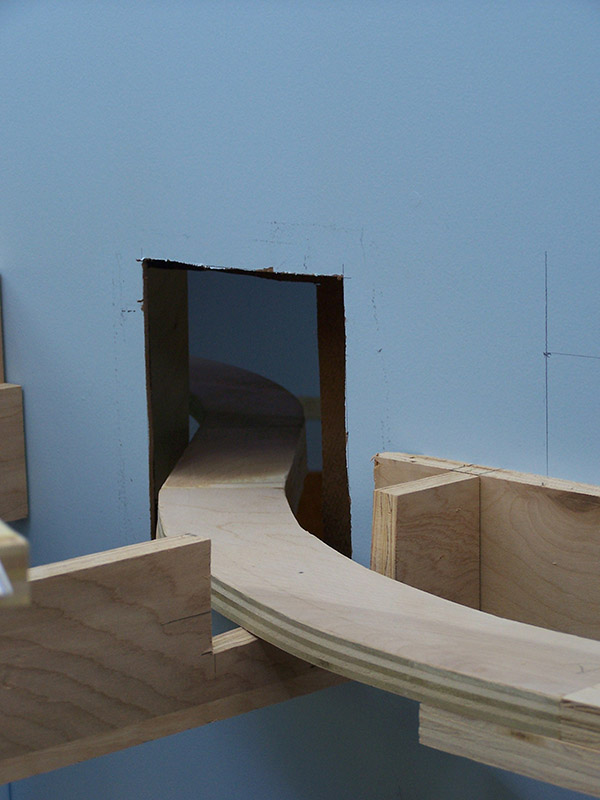
10 mile tunnel, or at least that is what it will feel like waiting for your train to emerge into Kitzmiller. Actually, 10 mile tunnel is the hidden track that connects the north end of staging on the lower deck with the layout at Kitzmiller on the upper deck. 10 mile tunnel starts at the north helix (as yet not built) rising up from staging. It snakes around under the Lapeer benchwork, crosses through the backdrop, runs hidden below Kitzmiller mountain, crosses through the backdrop again this time under the outer fringes of the rubber factory complex to finally make a 90º turn exiting out of the tunnel portal at Kitzmiller. Did you follow all that?
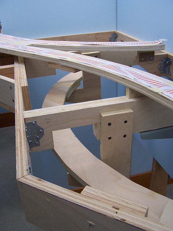
The entire path is at a near constant 1.7% grade. This was the magic number that permitted the necessary headroom when the tunnel route is under benchwork and, where the roadbed is in the benchwork, sufficient height so as not to have to cut all the way through a crossmember. The back and forth through the backdrop was necessary to go around the River Styx gorge. I don’t care much for multiple railroad bridges at different elevations across valleys as is so commonly seen on model railroads. So, instead of two bridges I will have one. The tunnel route detours around the valley by crossing sides of the backdrop.
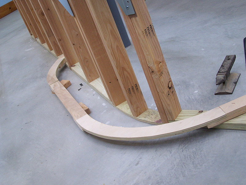
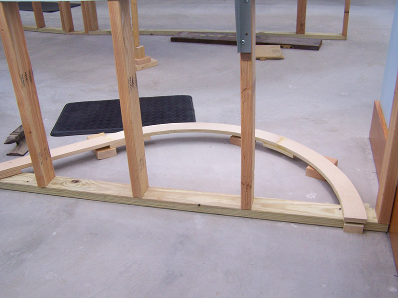
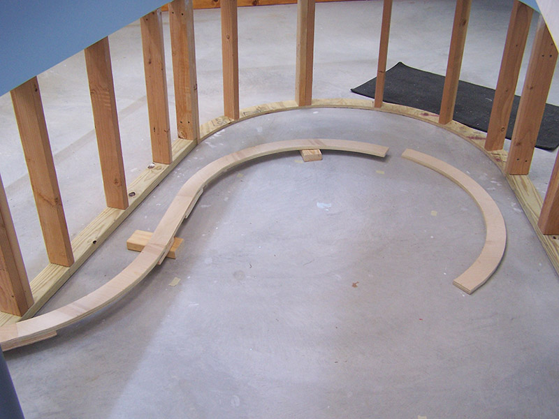
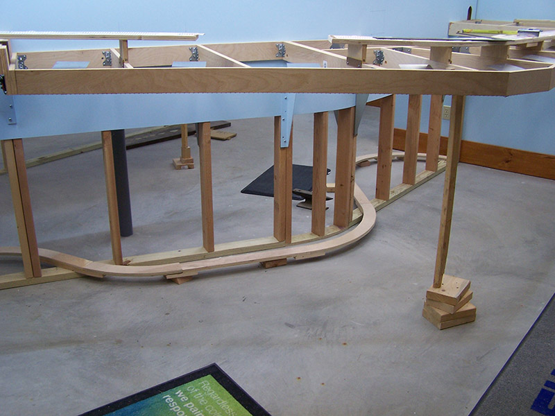
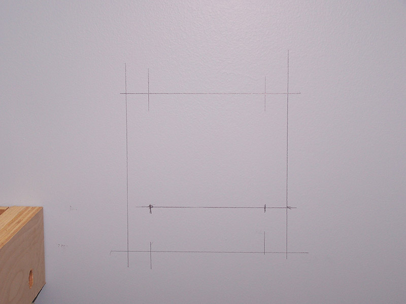
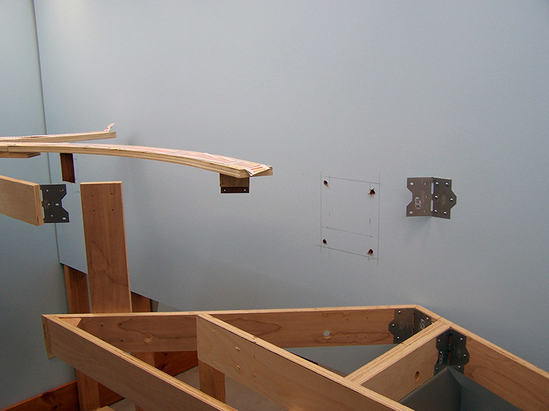
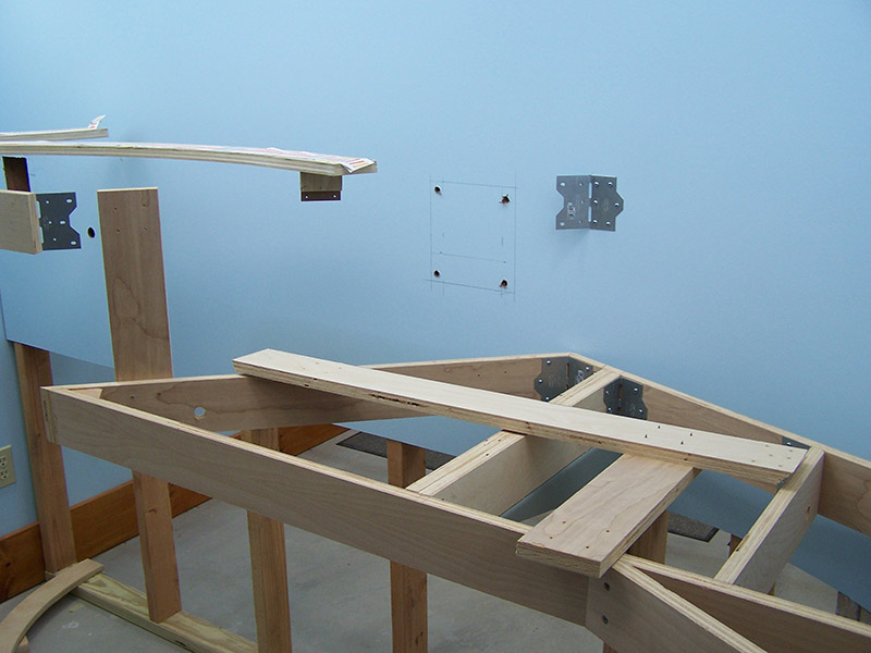
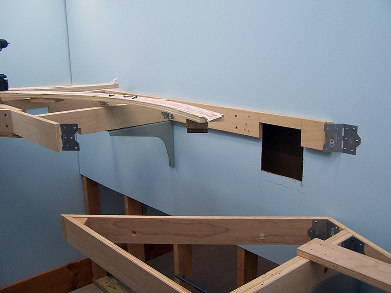
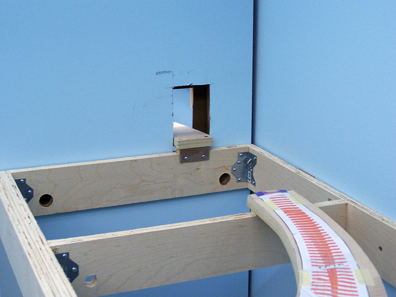
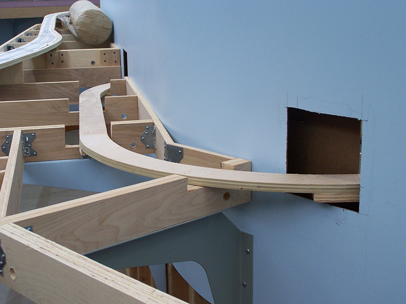
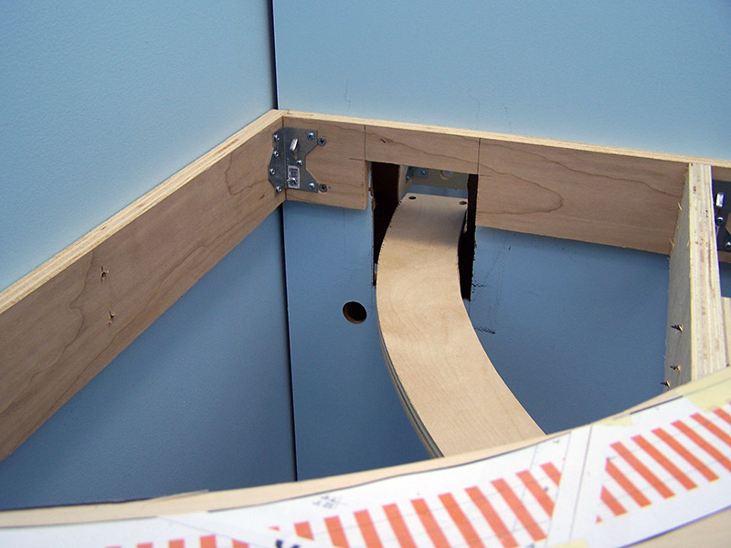
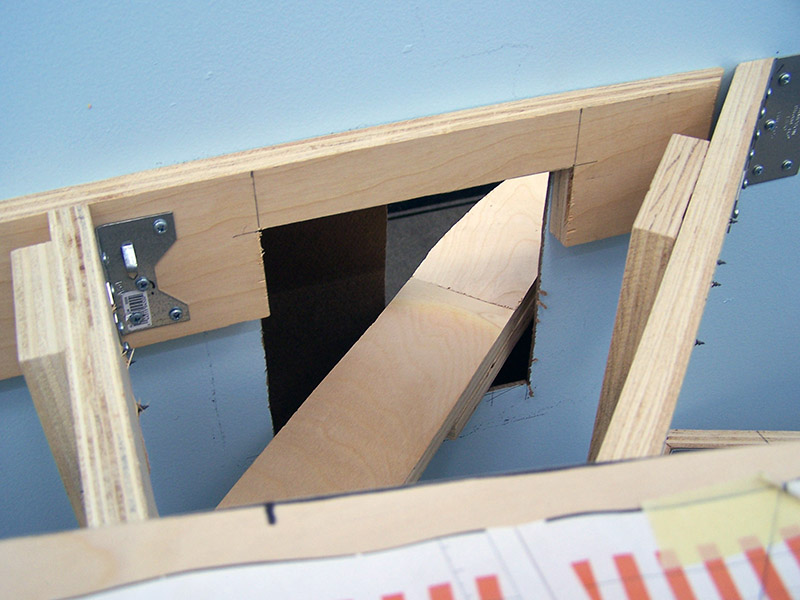
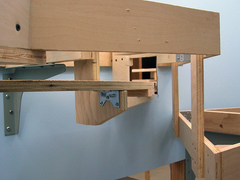
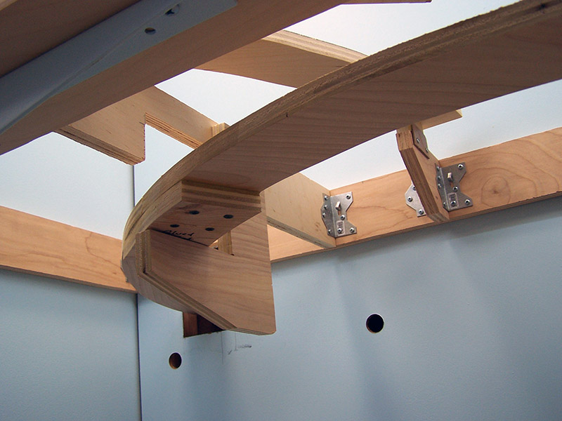
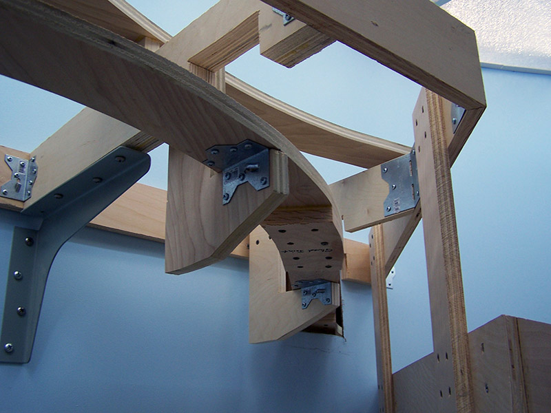
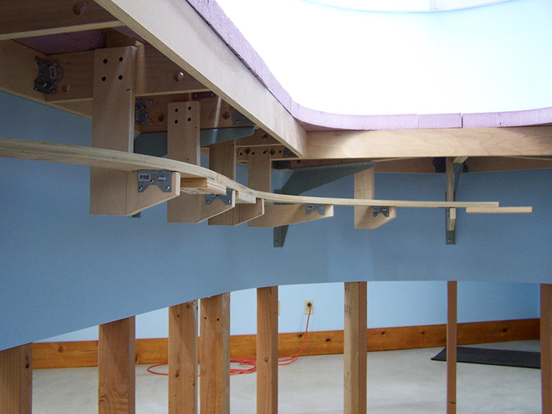
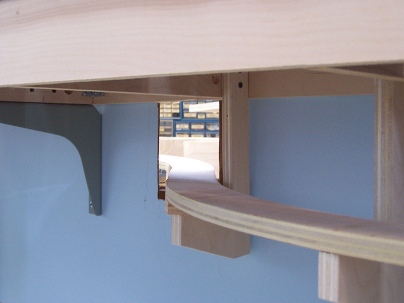
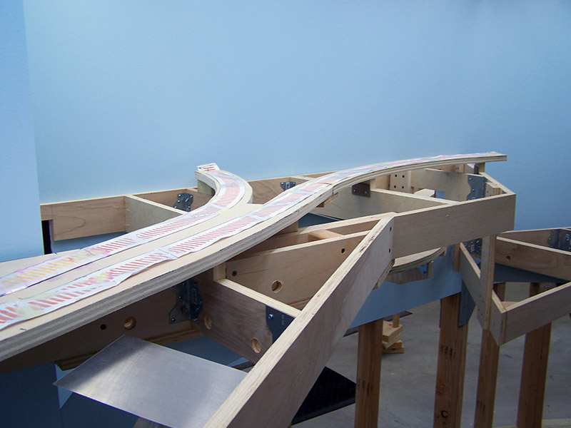
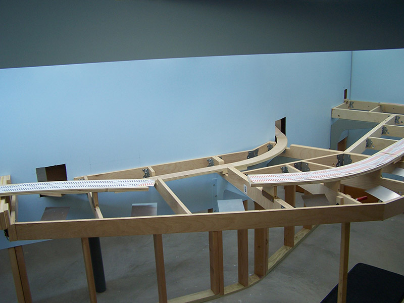
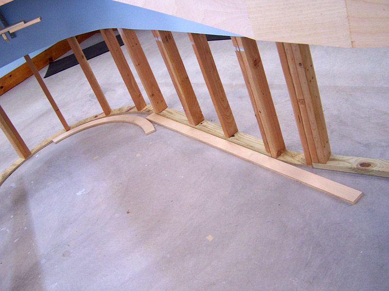
For this sub-roadbed construction I did not have a 1:1 XTrkCAD print as I did for the visible right-of-way. Instead, the tunnel route was built much like sectional train track is used. I cut several 24″ radius semicircles and a few straight sections all 3″ wide. Using a plumb bob from above to locate critical benchwork pieces, I laid out the “sectional” plywood pieces on the floor. Once the curves were in all the right places I then laid the straight sections on top of them and marked the tangents. Boards were cut and glued together with glued splice plates on the bottom. 1-1/4″ drywall screws from the bottom up reinforced the joints by making them both glued and screwed. Two joints were screwed only, no glue, so the whole sub-roadbed separates into two pieces otherwise it could never be fed through the openings due to the curves. Speaking of which, here is a situation where my angle bracket style of construction came in very handy. You can see in the pictures where I temporarily removed some benchwork to provide better access to the areas where I had to make cuts in the backdrop. The jig saw didn’t fit into the space so I simply took screws out of the angle brackets and removed benchwork pieces to open up the area. Reassembly was just as easy. Love construction with framing angles!
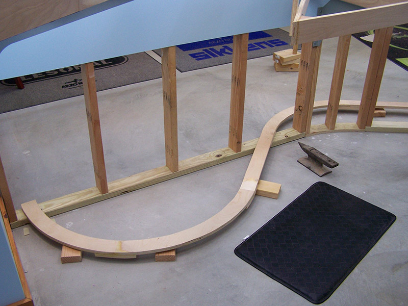
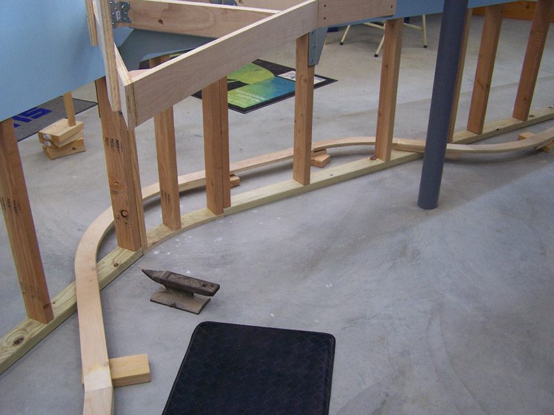
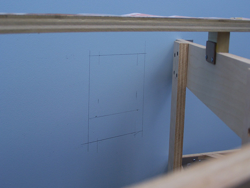
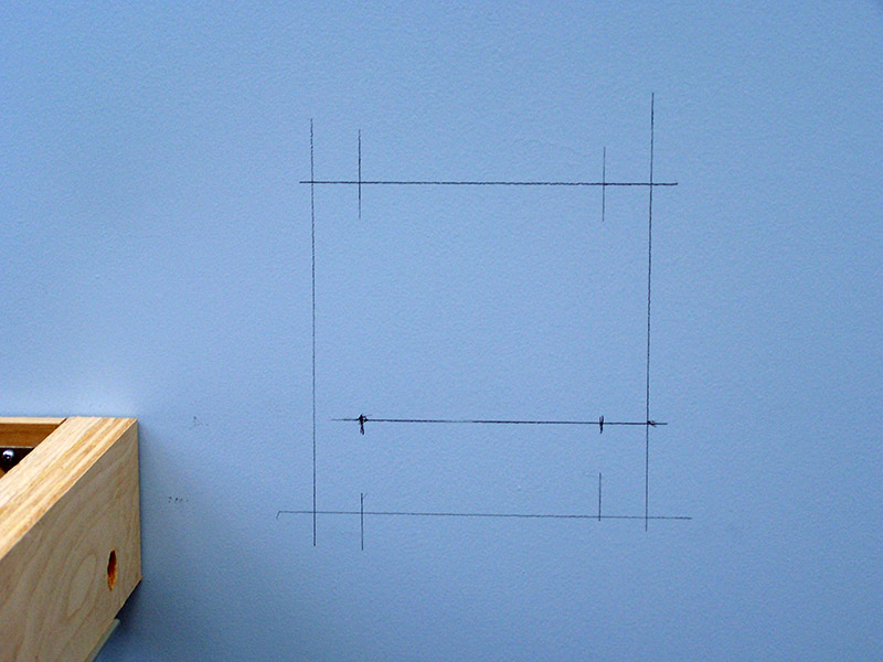
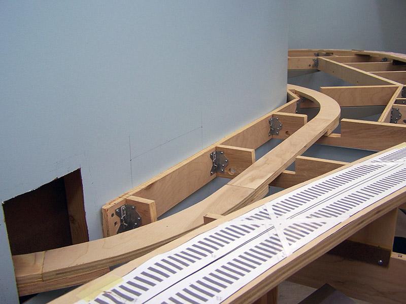
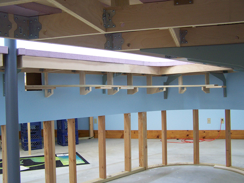
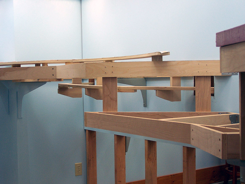
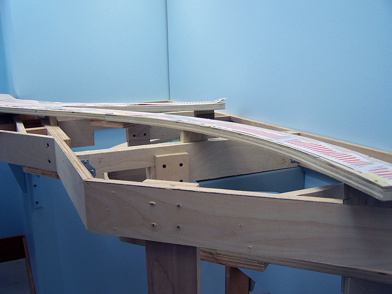
Once the complete sub-roadbed was assembled I then laid it in position on the floor again and used the plumb bob to mark on the sub-roadbed wherever it crossed a benchwork component. The horizontal locations of the backdrop openings were determined in the same manner. Next, my mason string was carefully laid down the middle of the sub-roadbed. I then marked the string at each point where it crossed over one of the marks from the previous step. The mason string was then laid straight and length measurements from the end were made. These length measurements allowed me to accurately calculate the height from the floor for a 1.7% grade. These measurements were then used to mark and cut the benchwork crossmembers, determine the drop of each hanging bracket, and mark the vertical locations of the backdrop openings. Just reading this makes it sound more complicated than it was. It was actually real simple to do and it made marking the cuts a no brainer. When the sub-roadbed was laid in place the grade became automatic. Checking with my iPhone level app verified the grade deviation is less than 0.2%. Plenty good enough for me. The loose end you see in the pictures is where the hidden track will connect to the north helix. I can’t make that final joint until the helix is in place.
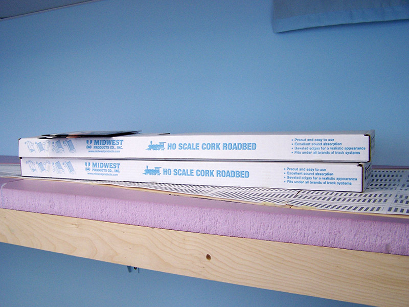
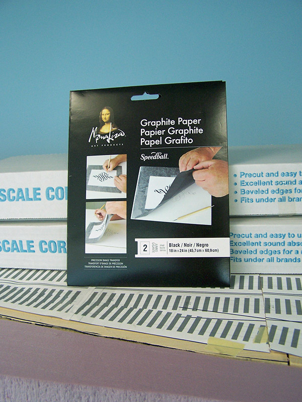
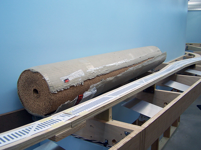
With the hidden sub-roadbed in place I could now complete the benchwork north of River Styx. Made a lot of sawdust but it is finished. Track laying can now begin. In preparation I purchased 2 boxes of 25 count Midwest cork roadbed and a 100 sq ft roll of 1/8″ cork sheet. Found graphite paper at Michaels to trace the track plan onto the plywood. Tracing the track plan is the next step.

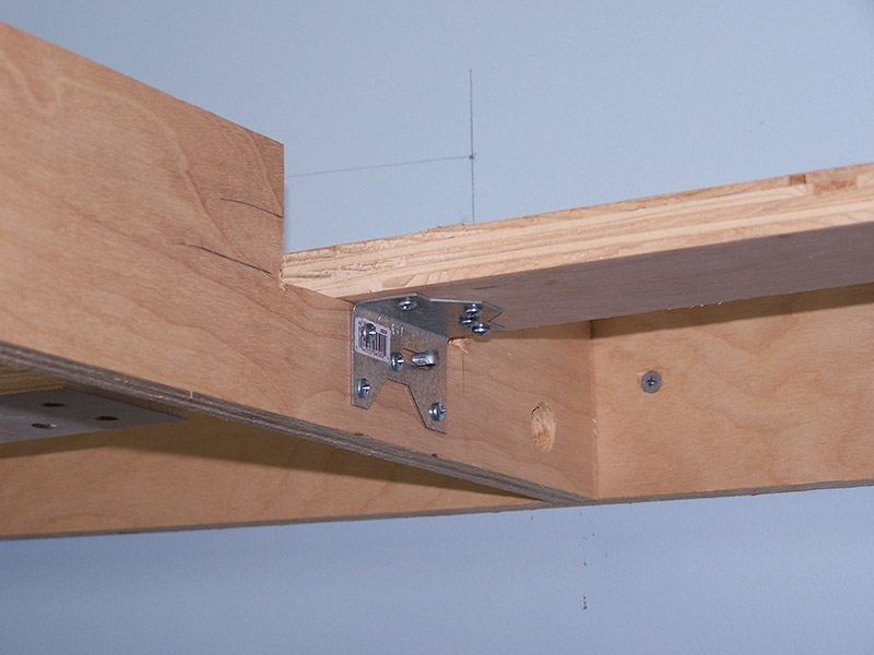

Where did you get the brackets holding the roadbed to the L braces? Thanks!
The brackets are framing angles. Simpson Strong-Tie A34.
http://www.homedepot.com/p/Simpson-Strong-Tie-18-Gauge-Framing-Angle-A34/100375340